98
MULTI V 5 Outdoor Unit Service Manual
Due to our policy of continuous product innovation, some specifications may change without notification.
©LG Electronics U.S.A., Inc., Englewood Cliffs, NJ. All rights reserved. “LG” is a registered trademark of LG Corp.
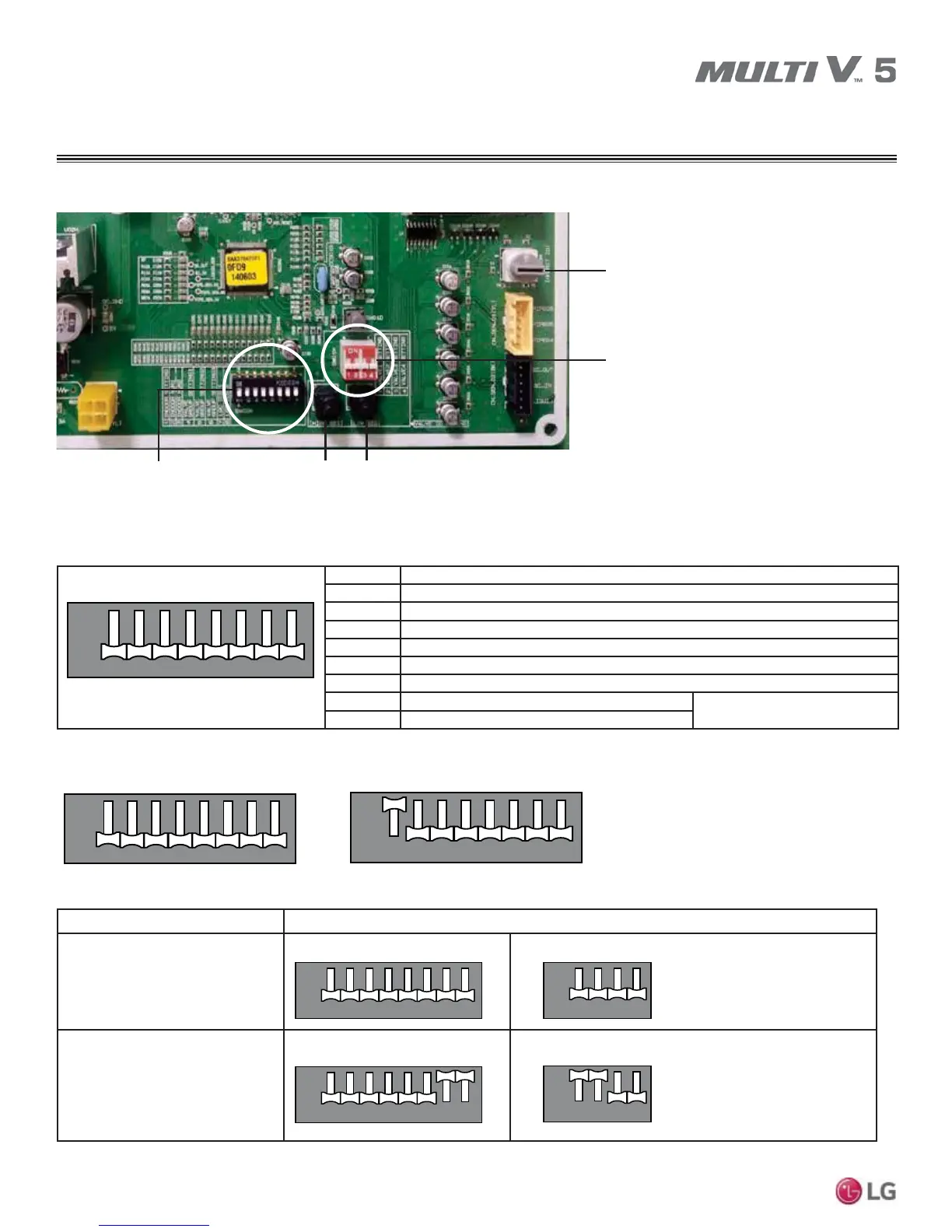
Figure 44: Close Up of DIP Switches and Rotary Dial on the Heat Recovery Unit Main PCB.
SW05M
SW01M
SW04MSW03M
(SW01M / SW03M / SW04M
Switches for Manual Valve Addressing)
SW02M
(DIP Switch for Set Up of Heat
Recovery Unit Functions)
ON S/W Selection
No. 1 Method for addressing the heat recovery control valves (Auto / Manual)
No. 2 Model of heat recovery unit
No. 3 Model of heat recovery unit
No. 4 Valve group setting
No. 5 Valve group setting
No. 6 Valve group setting
No. 7 Used only in factory production (preset to “OFF”)
Zone setting (“ON”)
No. 8 Used only in factory production (preset to “OFF”)
Selecting the Heat Recovery Unit Valve Addressing Method (Pipe Detection) (Auto / Manual).
Zone Control Setting.
DIP Switch Settings
Normal Control
Zone Control
1. Main Function of SW02M.
12 76543
1 2 7 86543
ON
OFF
8
1
1 2 7 86543
ON
OFF
Auto (Switch No. 1 on SW02M OFF)
2345 678
1
1 2 7 86543
ON
OFF
Manual (Switch No. 1 on SW02M ON)
2
3
4
5
6
7
8
1
1 2 7 86543
ON
OFF
2345678
1
1 2 7 86543
ON
OFF
2345678
1
12 43
ON
OFF
2
3
4
SW02M
SW02M
SW01M
1
12 43
ON
OFF
2
3
4
SW01M
Turn the DIP Switch of the zoned
branch to ON.
Example: Branches one (1) and
two (2) are set to zone control.
HEAT RECOVERY UNIT SETTINGS