214
MULTI V 5 Outdoor Unit Service Manual
Due to our policy of continuous product innovation, some specifications may change without notification.
©LG Electronics U.S.A., Inc., Englewood Cliffs, NJ. All rights reserved. “LG” is a registered trademark of LG Corp.
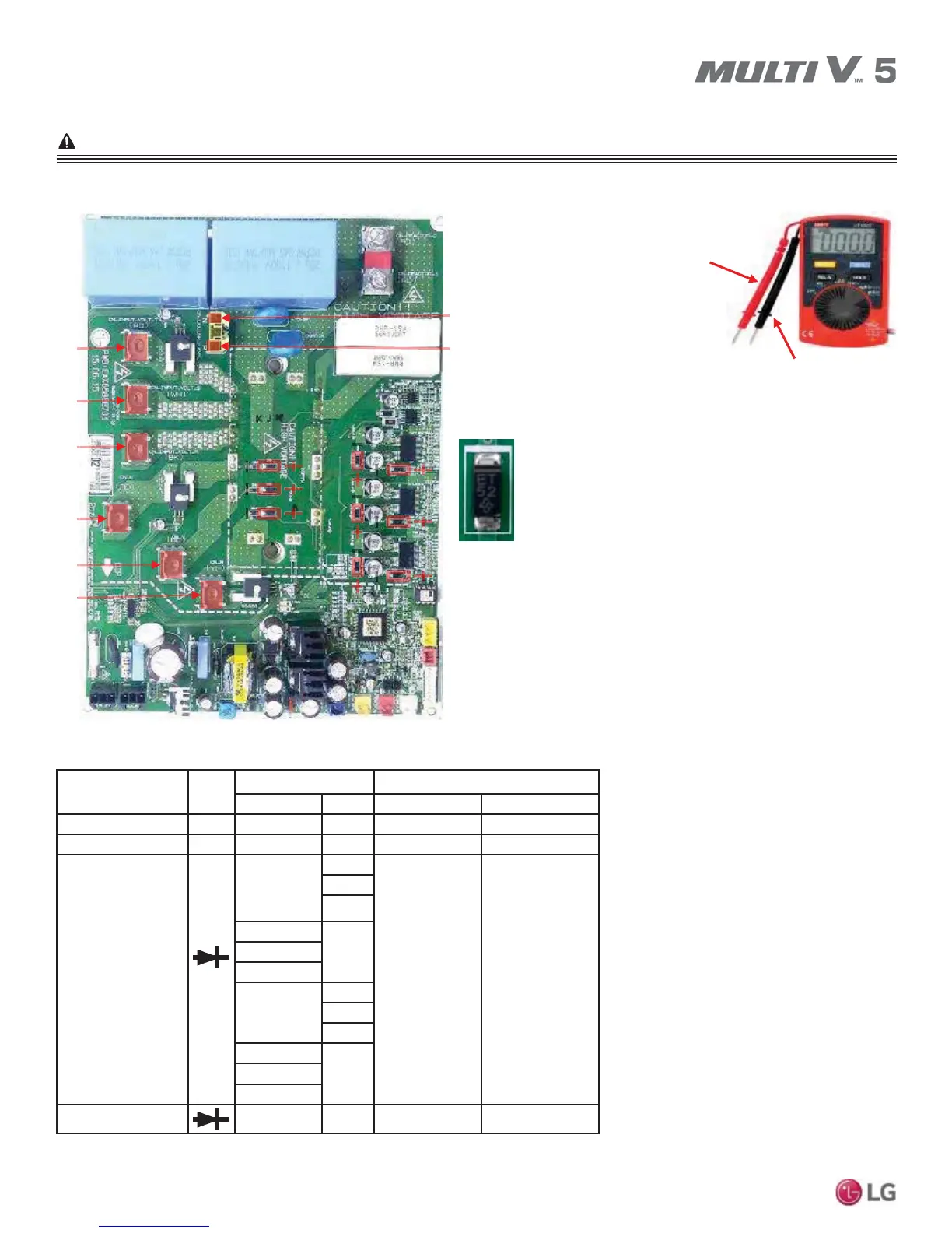
CHECKING INVERTER PCB IN CASE
OF POWER OFF
Please refer to the Safety Precautions on pages 4-7 for more detail to prevent injury or death regarding the operation and service
troubleshooting of the Multi V product.
WARNING
Figure 87: Checking Inverter PCB.
Red
Black
Figure 88: Multi-Meter.
N
R
S
T
U
V
W
P
BLACK (-)
RED (+)
Check Mode
Multi-Meter Measured Value
Black Red Normal Abnormal
5V Part Resistance ȍ GND 5V NĹ NĻa
15V Part Resistance ȍ GND 15V NĹ NĻa
IGBTM
P-(UVW)
U
0.38V ~ 0.7 V
Not normal
V
W
U
NV
W
P-(RST)
R
S
T
R
NS
T
Diode (9EA) - 0.38 ~ 0.7 V Not normal
Table 94: Inverter PCB Measurements.