144
MULTI V 5 Outdoor Unit Service Manual
Due to our policy of continuous product innovation, some specifications may change without notification.
©LG Electronics U.S.A., Inc., Englewood Cliffs, NJ. All rights reserved. “LG” is a registered trademark of LG Corp.
ERROR CODES
Please refer to the Safety Precautions on pages 4-7 for more detail to prevent injury or death regarding the operation and service
troubleshooting of the Multi V product.
WARNING
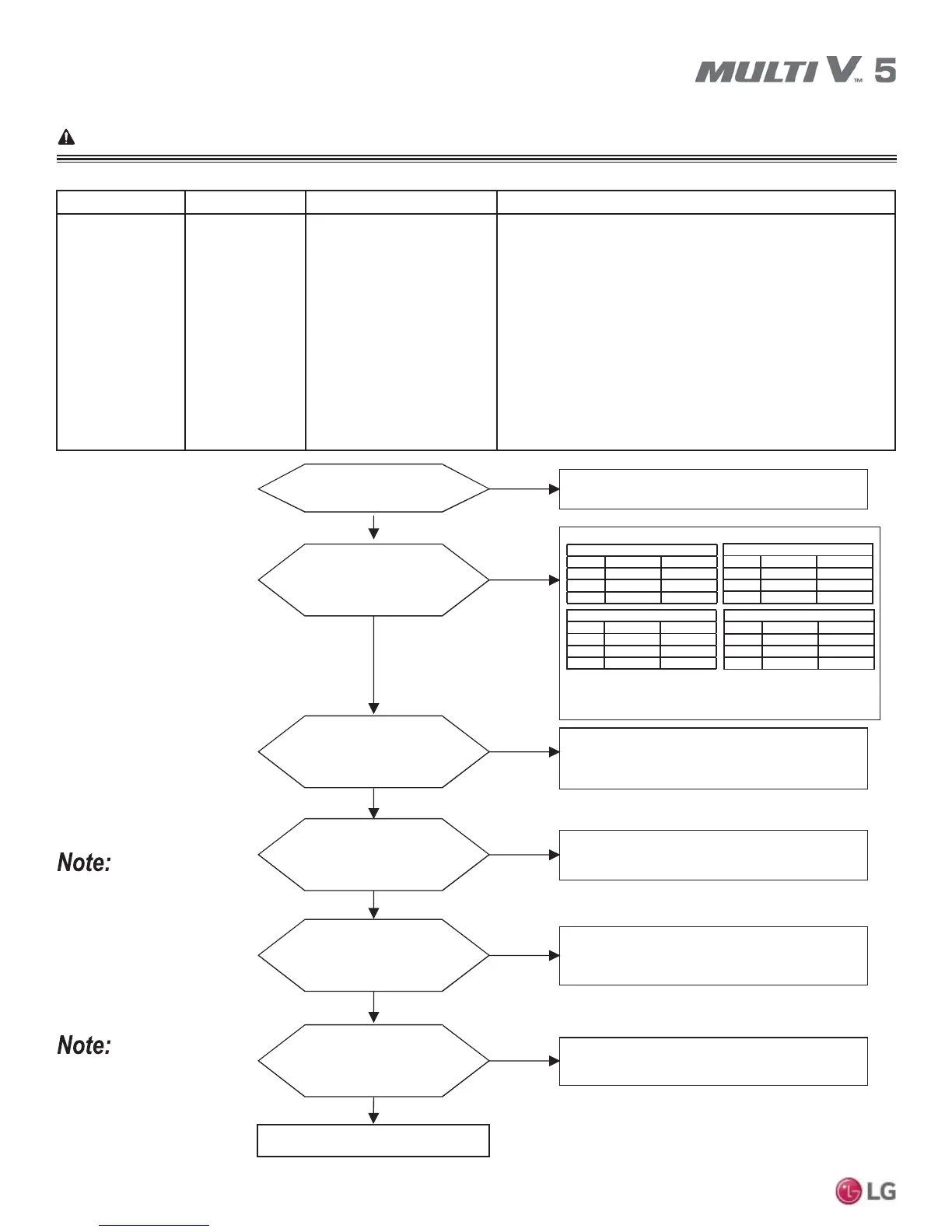
Error No. 21
Error No. Description Details Causes
21
Master: 211
Slave 1: 212
Slave 2: 213
Outdoor unit in-
verter board IPM
fault error.
• Inverter driver detects over-
current (CT sensor on the
IGBTM PCB).
• Error code is determined
by overcurrent in any one
phase of compressor.
1. Detected by the CT sensor on the IGBT PCB.
2. Overcurrent in compressor U-V-W phases.
3. Damaged compressor.
4. Damaged IPM on inverter board.
5. Compressor disconnected.
6. Damaged or disconnected cooling fan.
7. Damaged inverter board – input voltage too low. For 208-
230V: On 068 compressors = 143A for a minimum of 3μs;
on 048 compressors = 96A for a minimum of 3μs. For 460V:
On 068 compressors = 80 A for a minimum of 3μs; On 048
compressors = 56A for a minimum of 3μs. Also, see tables
below.
No
Yes
Yes
1. Check the resistance between each compressor terminal.
2. Check insulation resistance between compressor
WHUPLQDODQGSLSLQJ!0ȍ
ĺ
Are all the electrical wiring
connections correct?
No
Yes
1.
Check R(L1), S(L2), T(L3) wiring connections.
ĺ Rewire if errors are found.
No
Check if Inverter PCB assembly, IPM are operating
properly.
ĺ Replace Inverter PCB assembly if errors are found.
No
1.Check Inverter PCB assembly and U,V,W connections.
2. Check wiring for any disconnections or damage.
3. Check compressor terminal connections for bad contacts.
ĺ
Reassemble if errors are found.
1.Check Inverter PCB assembly and P,N connecti0ons.
2.Check wiring for any disconnections or damage.
ĺ
Reassemble if errors are found.
Yes
Yes
Are the DC link wiring
connections correct?
No
1.Check Inverter PCB assembly, compressor IPM heat sink
connections.
ĺ Reassemble if errors are found.
Yes
Are the compressor IPM heat
sink connections correct?
No
JQC068MA
Temp. 77°F 167°F
U-V ȍ ȍ
V-W ȍ ȍ
W-U ȍ ȍ
JQC048MA
Temp. 77°F 167°F
U-V ȍ ȍ
V-W ȍ ȍ
W-U ȍ ȍ
JQC068MB / JQC068MBA
Temp. 77°F 167°F
U-V 0.1ȍ ȍ
V-W 0.1ȍ ȍ
W-U 0.1ȍ ȍ
JQC048MB / JQC048MBA
Temp. 77°F 167°F
U-V 0.1ȍ ȍ
V-W 0.1ȍ ȍ
W-U 0.1ȍ ȍ
The resistance between
each phase and the inverter
compressor insulation resistance correct?
Are the compressor
wiring connections correct?
Recheck power and installation.
Is the inverter PCB assembly
functioning properly?
Replace compressor if problems are found.
Always apply heat transfer
paste to the new inverter PCB
heat sink before installing. For
instructions, see “Replacing
the Inverter PCB Heat Sink”
page later in this section.
See the “Checking the Inverter
Insulated-Gate Bipolar Transis-
tor Module” and the “Checking
the Phase Diode Bridge”
pages in the “Troubleshooting
Main Components” section.