143
Error Codes
Due to our policy of continuous product innovation, some specifications may change without notification.
©LG Electronics U.S.A., Inc., Englewood Cliffs, NJ. All rights reserved. “LG” is a registered trademark of LG Corp.
ERROR CODES
Please refer to the Safety Precautions on pages 4-7 for more detail to prevent injury or death regarding the operation and service
troubleshooting of the Multi V product.
WARNING
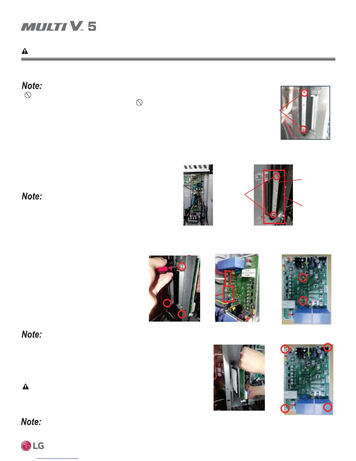
Error No. 10, continued.
'LVPDQWOLQJ6HUYLFLQJWKH&RQWURO%R[DQG,QYHUWHU3&%
• Do not remove the heat sink assembly before detaching the middle bracket screws.
• Use care when detaching the heat sink assembly. Do not apply excessive force. Applying excessive
force will damage the heat sink assembly and will cause the unit to malfunction.
Middle
Bracket
Screws
Heat Sink Assembly
Figure 64: Detaching the Middle
Bracket Screws.
Dismantling / Servicing the Control Box
1. Remove the control box cover.
2. Remove the middle bracket screws.
3. Gently detach the heat sink assembly from the control box.
4. Disconnect the fan lead wire from the control box, and detach the
compressor lead wires from the compressors.
5. Detach the outer screws, and then remove the control box as-
sembly from the outdoor unit.
6. To reassemble the control box, follow Steps 5 through 1 above.
Heat transfer paste at the heat sink is required. For instructions, see
“Replacing the Inverter PCB Heat Sink” page later in this section.
Middle
Bracket
Middle
Bracket
Screw
Heat Sink
Assembly
Figure 65: Removing the
Control Box Cover.
Figure 66: Removing the Middle Bracket
Screws.
Figure 67: Detaching the
Mounting Screws.
Figure 68: Disconnecting
the Compressor and
Power Input Wiring.
Figure 69: Detaching the
IGBT Screws.
Figure 70: Removing the
Inverter PCB.
Figure 71: Removing the
PCB.
Images here are representative of system components. Actual component appearance depends on model and system type.
1.
• Only use a JIS screwdriver. A standard Phillips screwdriver will damage / strip
the inverter PCB screw heads.
• Heat transfer paste at the heat sink is required. For instructions, see “Replac-
ing the Inverter PCB Heat Sink” page later in this section.
• Carefully reconnect the wires with out interchanging the locations.
WARNING
Dismantle the Control Box and Inverter PCB only when power is OFF. Electrical
shock can cause physical injury or death.
Dismantling / Servicing the Inverter PCB
1. Detach the four (4) thermal pad mounting screws
at the left side of the control box.
2. Disconnect the compressor (U/V/W) and the pow-
er input (R/S/T) lead wiring.
3. Detach the two (2) middle IGBT mounting
screws.
4. Remove the Inverter PCB from the control box
assembly.
5. Remove the PCB from the corner supports.
6. To reassemble the Inverter PCB, follow Steps 5
through 1 above.