120
MULTI V 5 Outdoor Unit Service Manual
Due to our policy of continuous product innovation, some specifications may change without notification.
©LG Electronics U.S.A., Inc., Englewood Cliffs, NJ. All rights reserved. “LG” is a registered trademark of LG Corp.
&KHFNLQJWKH,QYHUWHU,QVXODWHG*DWH%LSRODU7UDQVLVWRU,*%7,QWHOOLJHQW
Power Module (IPM)
1. Shut off main power. After main power is shut off, wait at least
ten (10) minutes until inverter compressor PCB DC voltage is
discharged.
5HGDQG%ODFNDUHWKHPXOWLWHVWHUWHUPLQDOV
P Terminal: Black (-) N Terminal: Red (-)
U Terminal : Red (+) 0.2 ~ 0.6 V -
V Terminal : Red (+) 0.2 ~ 0.6 V -
W Terminal : Red (+) 0.2 ~ 0.6 V -
P Terminal: Red (+) N Terminal: Red (+)
U Terminal : Black (-) - 0.2 ~ 0.6 V
V Terminal : Black (-) - 0.2 ~ 0.6 V
W Terminal : Black (-) - 0.2 ~ 0.6 V
Table 65: Checking the Inverter IGBT / IPM.
2. Disconnect all IGBT / IPM connections.
3. Set the multi-tester to diode mode.
4. Measured value must be 0.2 ~ 0.6 V as shown in the table
below.
5. If the measured value is different than what is listed in the table
below, then set the multi-tester to resistance mode and measure
DJDLQ,IWKHYDOXHLVWRRORZȍRUWRRKLJKKXQGUHGV0ȍWKH
inverter PCB is damaged and needs to be replaced.
After switching off the main power supply and verifying that the DC volt-
age was discharged, wait for at least ten (10) minutes before checking
the electrical components in the control box. There is risk of electric
shock, physical injury or death.
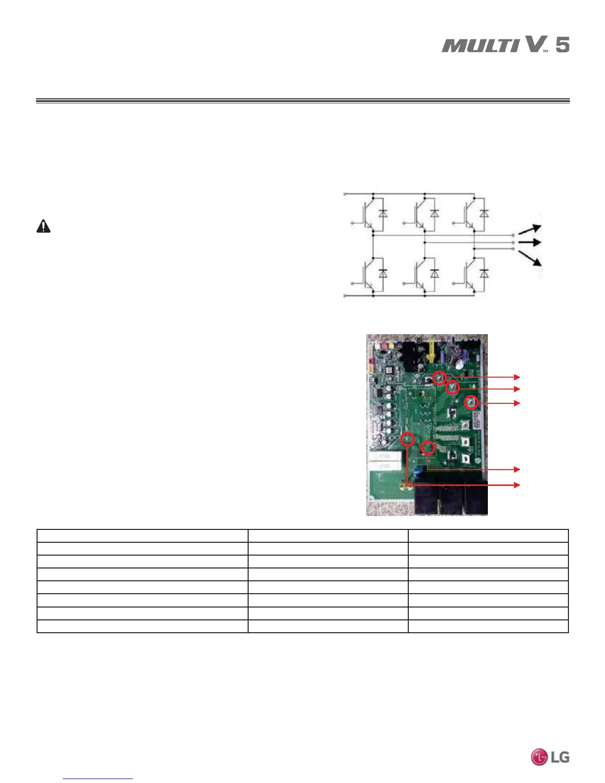
&+(&.,1*7+(,19(57(5,*%7,30
U
V
W
P
N
WARNING
Figure 57: 6LPSOL¿HG'LDJUDPRIDQ,QYHUWHU,*%7,30
N
P
W
V
U
Figure 58: Location of IGBT / IPM Terminals (Appearances Will Vary
Depending on Model).