64
MULTI V 5 Outdoor Unit Service Manual
Due to our policy of continuous product innovation, some specifications may change without notification.
©LG Electronics U.S.A., Inc., Englewood Cliffs, NJ. All rights reserved. “LG” is a registered trademark of LG Corp.
&RRO+HDW6HOHFWRU)Q
The setting communicates to the outdoor unit that the optional LG Cool / Heat Selector (or appropriate
¿HOGSURYLGHGUHOD\VDQGZLULQJWKDWSHUIRUPWKHVDPHWDVNis connected to the system. The Cool / Heat
Selector is field-wired to the “Dry 1” and “Dry 2” terminals located on the master outdoor unit main PCB.
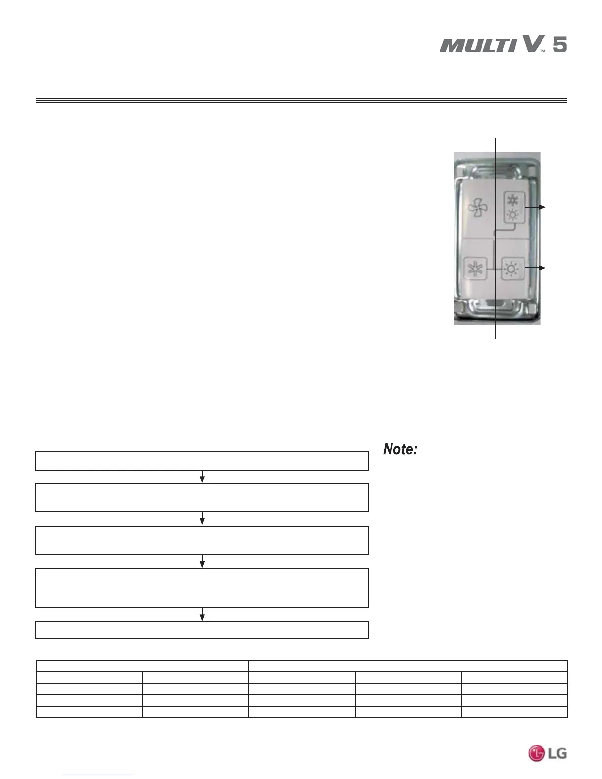
The Cool / Heat Selector has two switches. The two-position upper switch manually locks out heating and
cooling operation, allowing fan only, or heating or cooling operation depending on the position of the low-
er switch. The two-position bottom switch and manually sets the position of the outdoor unit’s reversing
valve. If the left side is depressed, the valve is in the cooling position. If the right side is depressed, the
valve is in the heating position. The Cool / Heat Selector also provides a method for locking out compres-
sor operation by placing the “Fan Only” toggle switch in the “On” position.
• Off (Default): No Cool / Heat Selector installed, or the Cool / Heat Selector is installed, but has not been
identified by the master outdoor unit.
• On: Cool / Heat Selector installed and operational. When On is selected:
• The left side of the upper switch is depressed. Mechanical refrigeration is locked out and the indoor
unit fans are allowed to operate. The position of the lower switch is irrelevant.
• The right side of the upper switch is depressed, the lower switch has the right side depressed, and the
system is operating in cooling.
• The right side of the upper switch is depressed, the lower switch has the left side depressed, and the
system is operating in heating.
Use the Cool / Heat Selector in heat pump systems to set the system mode for all cooling operation, all heating operation, fan only, or dry
operation (when all indoor units have to be in the same mode).
For use in heat pump systems only.
Turn No. 5 on the master outdoor unit PCB DIP switch bank SW01 to ON.
6HOHFWWKH³)XQF´PRGHE\XVLQJWKH6:&IRUZDUGŹEXWWRQDQGWKH6:&EDFNZDUG
ŻEXWWRQDQGWKHQSUHVVWKH6:&FRQILUPƔEXWWRQ
6HOHFWWKH³)Q´IXQFWLRQE\XVLQJWKH6:&IRUZDUGŹEXWWRQDQGWKH6:&EDFNZDUG
ŻEXWWRQDQGWKHQSUHVVWKH6:&FRQILUPƔEXWWRQ
Select from “oFF”, “op1,” or “op2” options (see table below) by using the SW03C forward
ŹEXWWRQDQGWKH6:&EDFNZDUGŻEXWWRQDQGWKHQSUHVVWKH6:&FRQILUPƔ
button.
The Cool / Heat Selector function is set. PCB does not need reset.
• The Cool / Heat Selector must be installed
first before setting the cool / heat operation
function.
• A trained LG service provider must set this
function during system installation.
• If cool or heat function is not used, set to OFF.
• Cool / Heat Selector is flagged as the master
on the central control communications bus.
• Cool / Heat Selector is not for use with BMS
Gateway, VMS, or VMS Communications
Manager.
Switch Control Function
Switch (Up) Switch (Down) oFF op1 (Mode) op2 (Mode)
Right Side (On) Left Side (On) Not Operating Cooling Cooling
Right Side (On) Right Side (On) Not Operating Heating Heating
Left Side (Off) - Not Operating Fan Mode Off
Figure 10: Cool / Heat Selector.
Left Side
Switch
(Up)
Right Side
Switch
(Down)
Table 23: Cool / Heat Selector Function Settings.
Figure 11: Setting the Cool / Heat Selector Function.
OTHER CONTROLS
Setting Optional Modes