152
MULTI V 5 Outdoor Unit Service Manual
Due to our policy of continuous product innovation, some specifications may change without notification.
©LG Electronics U.S.A., Inc., Englewood Cliffs, NJ. All rights reserved. “LG” is a registered trademark of LG Corp.
ERROR CODES
Please refer to the Safety Precautions on pages 4-7 for more detail to prevent injury or death regarding the operation and service
troubleshooting of the Multi V product.
WARNING
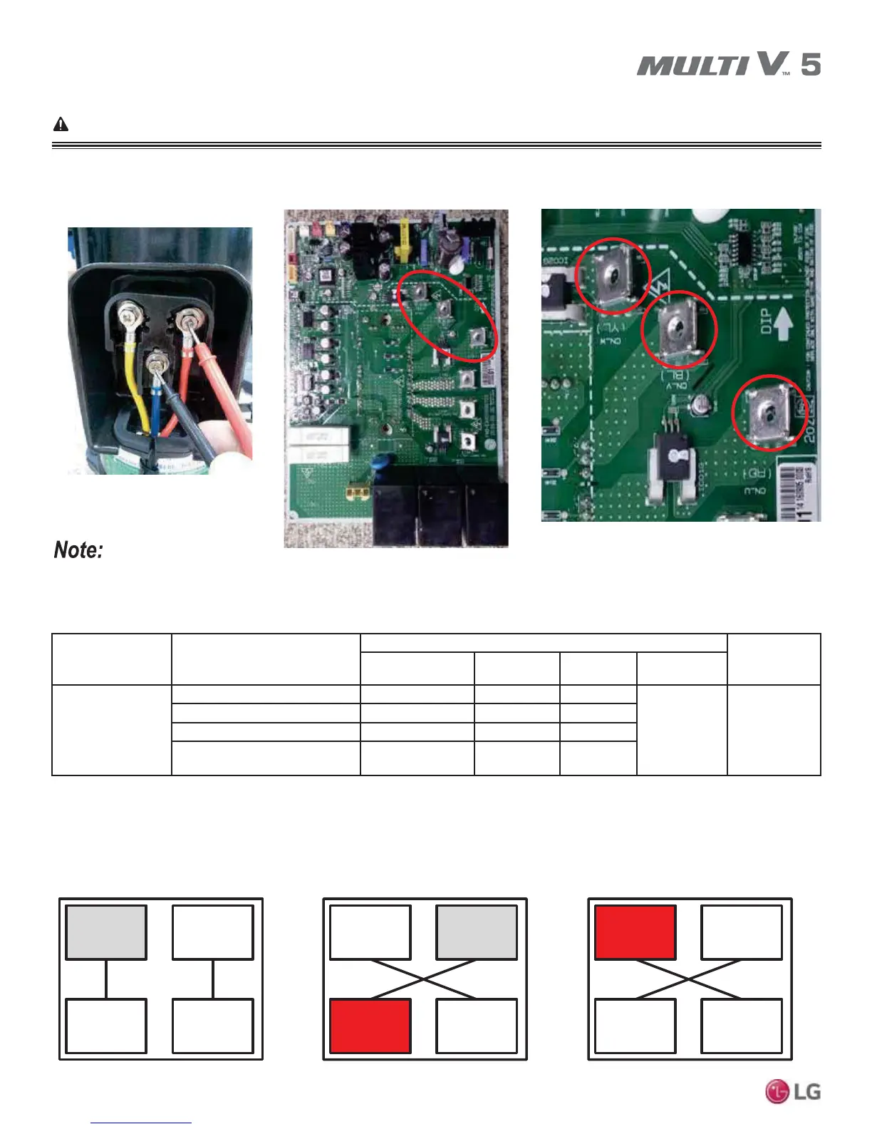
Error No. 26, continued.
Measure resistance between
compressor terminals.
Compressor wiring connections.
Images here are representative of system components. Actual component appearance depends on model and system type.
Table 80: Error No. 26 Checkpoint Details.
Cause Check
Checklist
App.
Check Point Normal Abnormal
Defective
Parts
Inverter PCB
Damaged
Check Inverter PCB appearance Appearance Good Damage
Inverter PCB B1 (Power Off)
Measure 5V,15V line 5V, 15V Resistance NĹ NĻa
IGBTM (Check IGBT) P-U,V,W / N-U,V,W 0.38V ~ 0.7V Non-normal
Inverter Drive Circuit
(Check diode)
Diode 0.38V ~ 0.7V Non-normal
Figure 73: Two Compressor Additional Check Procedure (Same Capacity Inverter Only).
Inv.1
- CH26
Inv.2
Comp.1 Comp.2
Inv.1
- CH26
Inv.2
Comp.1 Comp.2
Inv.1
Inv.2
- CH26
Comp.1 Comp.2
Standard Connection.
Example: Inverter 1, CH26
displayed.
If Inverter 2 has CH26 displayed,
then Comp. 1 is defective.
If Inverter 1 consistently displays
CH26, then Inverter 1 is defective.
Cross Connections after Operation.
or