Electrical Connections
14 Liebert
®
NX
™
3.1.2 UPS Input Configuration
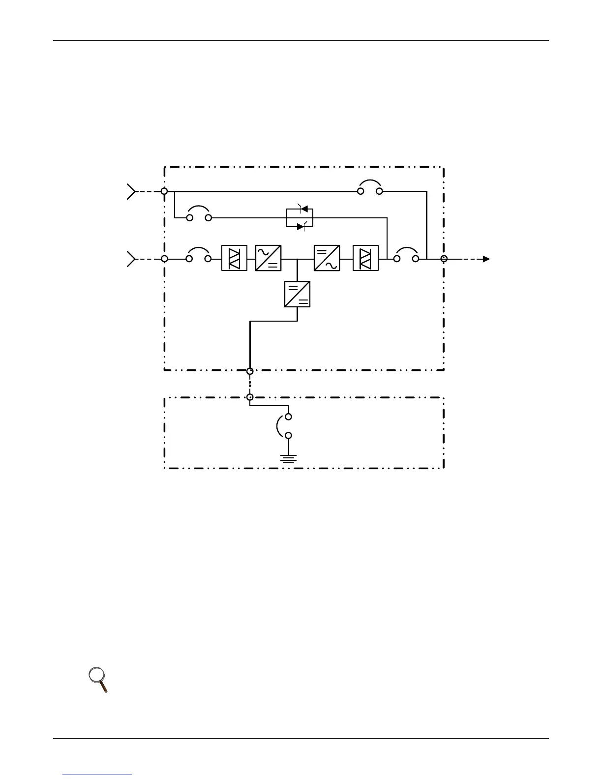
Figure 3 illustrates the Liebert NX in a split bypass (dual-input) configuration. In this configuration,
the Static Bypass and the Maintenance Bypass lines are supplied from a separate feed from the Main
input. Both sources must be protected externally with properly sized protective devices. By default,
the unit ships with internal links installed between the bypass input and main input (Single Input
configuration). To wire the unit as a dual input UPS, remove the links and wire the bypass to the
input bus bars, then wire the main input directly to CB1 (see Figure 3).
Figure 3 Single module block diagram—dual input configuration
3.1.3 Cabling Guidelines
The following are guidelines only and are superseded by local regulations and codes of practice where
applicable. Use wiring rated at 75°C or greater.
1. The ground conductor should be sized in accordance with the input overcurrent protection device
data in Table 8. The ground cable connecting the UPS to the main ground system must follow the
most direct route possible. Control wiring and power wiring must be run in separate conduit.
Output and input cables must be run in separate conduit.
2. Consider using paralleled smaller cables for heavy currents—this can ease installation.
3. When sizing battery cables, a maximum voltage drop of 4VDC is permissible at the current
ratings in UPS terminal. For terminal connection sizing, see Table 8.
4. In most installations, especially parallel multi-module systems, the load equipment is connected
to a distribution network of individually protected busbars fed by the UPS output, rather than
connected directly to the UPS itself. When this is the case, the UPS output cables can be rated to
suit the individual distribution network demands rather than being fully load-rated.
5. When laying power cables, do not form coils; this will help avoid increasing formation of
electromagnetic interference.
NOTE
If more load is added to the distribution panel, the unit’s cabling must be resized.
3-Phase
3W + Gnd
3-Phase
3W + Gnd
AC Input
AC Output
3-Phase
3W + Gnd
Battery Cabinet
2W + Gnd
UPS Cabinet
Converter
InverterRectifier
Static Bypass
Internal Maintenance Bypass