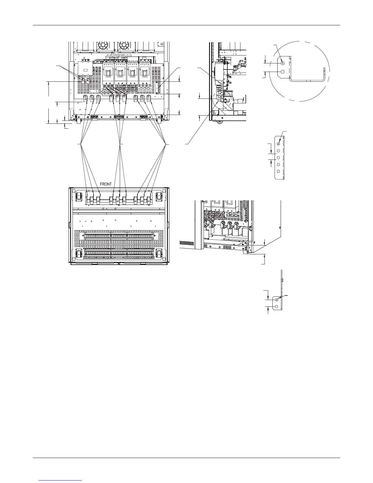
1. All dimensions are in inches [mm].
2. 24" [610] minimum clearance above unit required
for air exhaust and 36" [914] minimum service clearance at front of unit.
3. Keep cabinet within 15 degrees of vertical.
4. Top and bottom cable entry available through removable access
plates. Remove, punch to suit conduit size and replace.
5. Control wiring and power wiring must be run in separate conduits.
6. Aluminum and copper-clad aluminum cables are not recommended.
7. All wiring is to be in accordance with national and local electrical codes.
8. Terminal connecting hardware included.
BOTTOM CABLE ENTRY
3.9 (100)
Access Plate Height
DETAIL A
Input/Output/Bypass
GROUND BUS
DC BUS
Rear
BOTTOM VIEW
U389641
Rev. 0
RIGHT SIDE FRONT
Right Front Corner
Post Not Shown
Main Input Bus
See Detail A
Bypass Input Bus
(Dual Input)
See Detail A
Output
Bus
See Detail A
FRONT
LOWER
Ø .39
(10) Typ
Ø .39
(10) Typ
Ø .39
(10) Typ
DC
Bus
Ground
Bus
20.3
(516)
10.6
(268)
10.1
(258)
8
(203)
Typ
5.9
(150)
1.6
(40)
1
(25)
Typ
1
(25)
Typ
1
(25)
Typ