EasyManuals Logo

Liebert NX User Manual

Liebert NX
132 pages
To Next Page IconTo Next Page
To Previous Page IconTo Previous Page
Page #85 background imageLoading...
Page #85 background image
Installation Drawings
Liebert
®
NX
75
Figure 49 Lineup detail—Configuration CB2, CB3, CB4 parallel connection to Liebert NX
C1-C4
E1-E4
B1-B4
C1-C4
G1-G4
H1-H4
D
E1-E4
F
FRONT
Without Covers
FRONT
Door Open
G1-G4
H1-H4
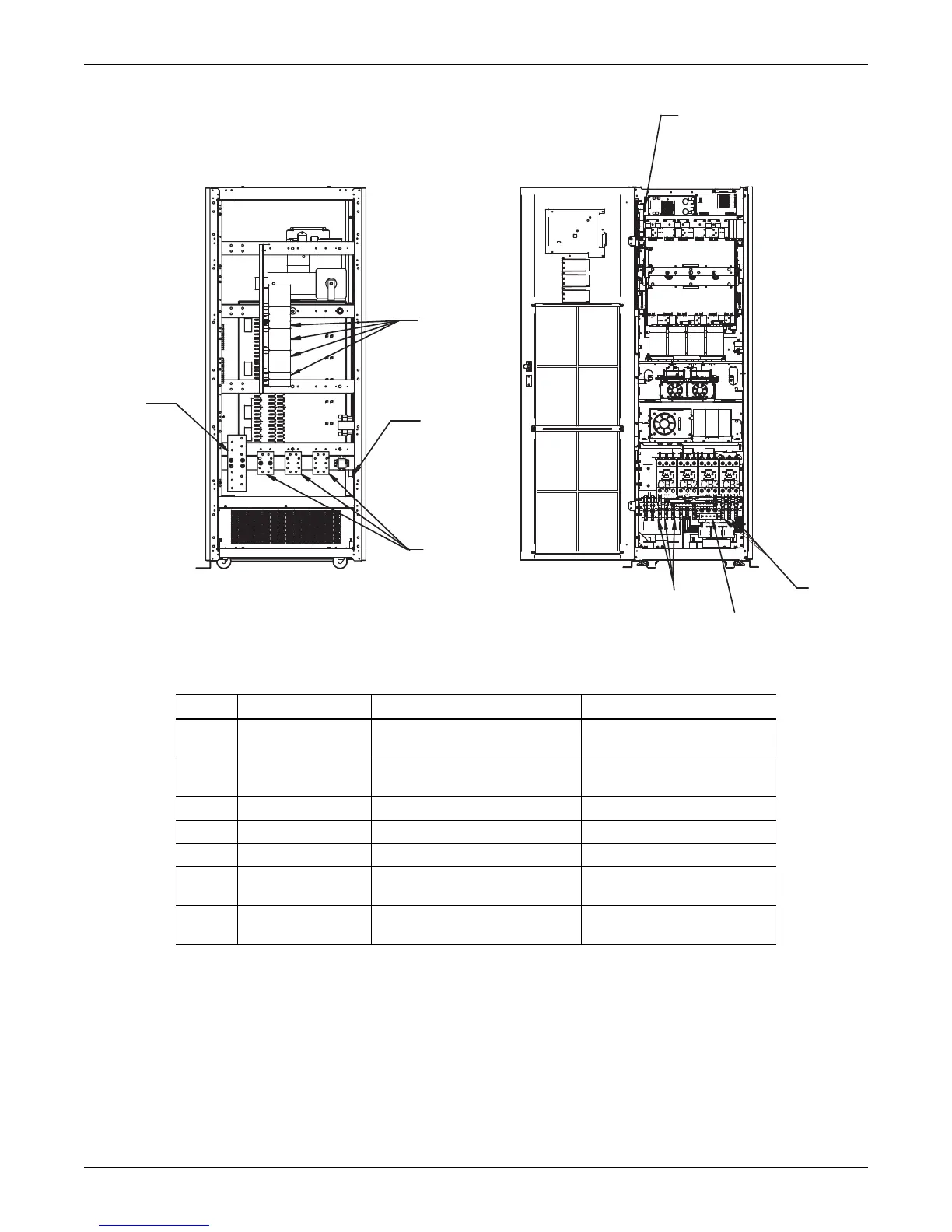
Run From To Conductors
B1-B4 Utility
UPS #1-UPS #4 Module AC
Input
Ph A, B, C - UPS Inputs
C1-C4
UPS #1-UPS #4
Module AC Output
Parallel Cabinet Ph A, B, C - UPS Outputs
D Parallel Cabinet Critical Loads Ph A, B, C - System Outputs
E1-E4 Parallel Cabinet UPS #1-UPS #4 Module Gnd Ground - UPS
F Parallel Cabinet Building Gnd Ground - System
G1-G4 Parallel Cabinet
UPS #1-UPS #4 Module
UPS Parallel Logic Board (M3)
Output Breaker Aux Contact
H1-H4 Parallel Cabinet
UPS #1-UPS #4 Module
UPS Parallel Logic Board (M3)
UPS Bypass Detection

Table of Contents

Questions and Answers:

Question and Answer IconNeed help?

Do you have a question about the Liebert NX and is the answer not in the manual?

Liebert NX Specifications

General IconGeneral
Frequency50/60 Hz
TopologyDouble Conversion/Online
Input Voltage208, 220, 240 VAC
Output Voltage208, 220, 240 VAC
Battery TypeVRLA
Operating Temperature0 to 40°C (32 to 104°F)
Humidity Range0 to 95% (non-condensing)

Related product manuals