SCPC System • Replacing components
50 CP_SEM_60-03-00.002
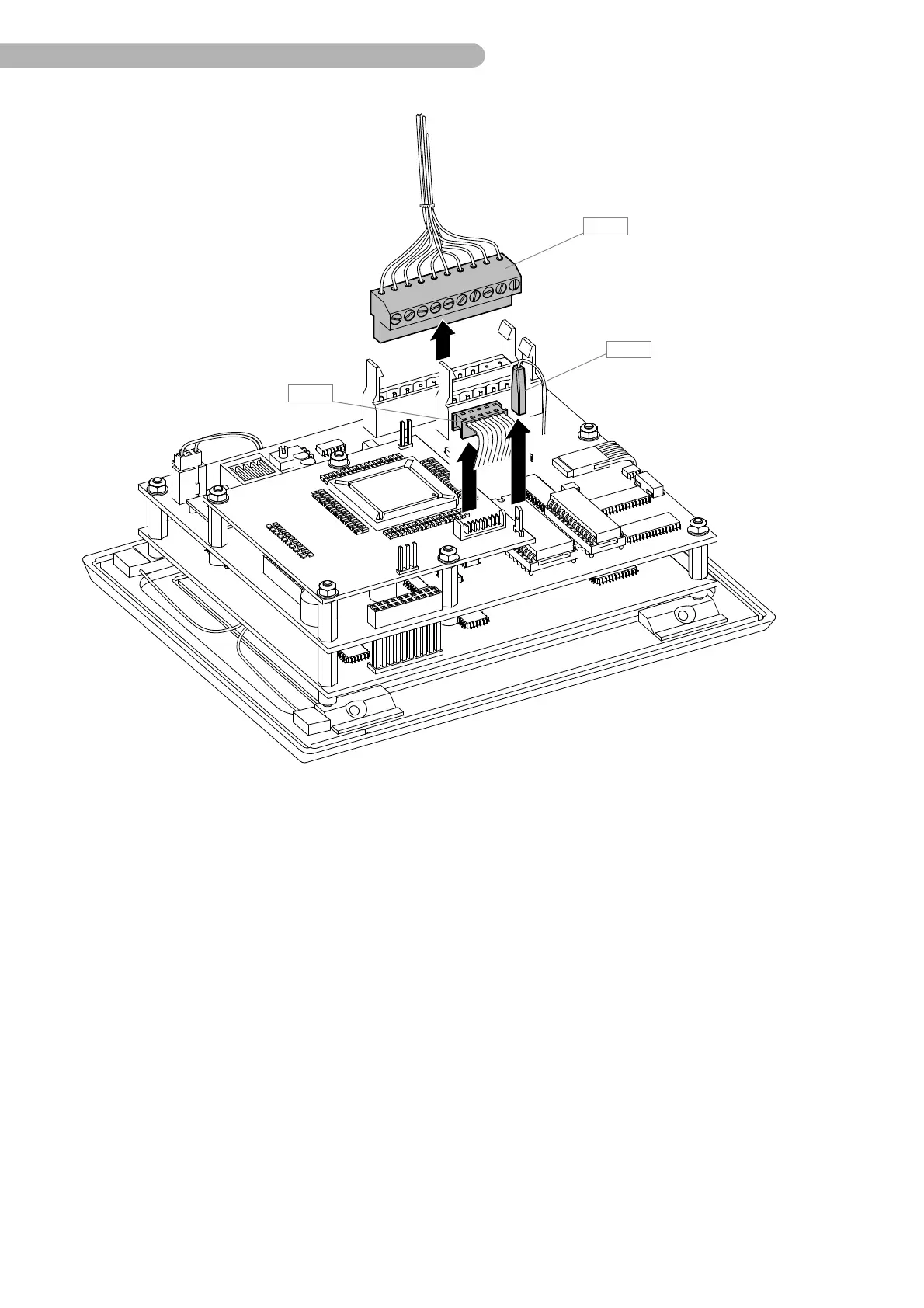
fig. 20: Arranging the touch screen module
◗ Remove the connector B 5 (CPU circuit board to backplane circuit board), B 14 (serial interface flat
cable) and B 15 (Interface circuit board to Backplane circuit board).
◗ Carefully place the touch screen module on a soft, level surface with the display surface facing
downwards. Ensure that the screen is not scratched.