CHAPTER 6: OPERATION 75
QUICK LOAD SERVO 80 S2
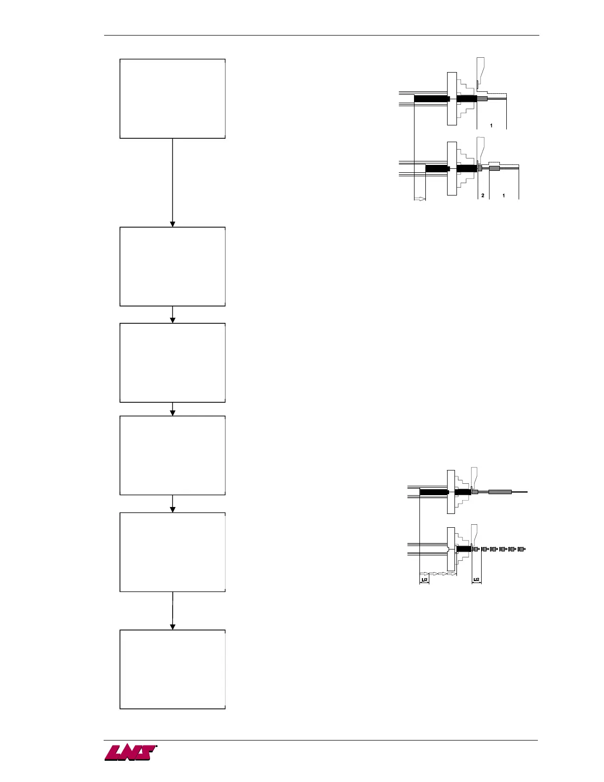
Number of clamping device openings to machine the part
When there is multiple openings
required to machine a piece (1 and
2), interface conflicts can occur
during the bar feed. If for instance,
the bar feed is controlled by the
clamping device signal, it might
occur when the piece is not
finished.
It is important that the bar feed
system keeps track on the number
of openings of the clamping device
during the machining of the piece.
For this type of machining, the lathe
controls the feed-out of the piece.
Top-cut position
During the loading cycle, the bar is automatically loaded and positioned
into the spindle, outside the clamping device of the lathe (chuck or
actuator). This positioning corresponds to a value (Z)programmed by the
operator, which is equal to the distance between the measuring cell and
the position of the material in the lathe clamping device.
Pusher reverse distance after feeding
In production cycle, each time the clamping device of the lathe closes,
the feeding pusher moves backwards so as not to come into contact with
the rotating bar. The value of the reverse distance is set at 4 mm at the
factory.
1. Default value (4 mm)
2. Outside of the spindle
3. Enter the desired value
Optional auxiliary end of bar (option)
When machining remnants (A) that are rather long, a second mode of
production for machining the rest of the stock can be selected
(depending on the capabilities of the lathe).
Part feed out length after aux. EOB (option)
When machining remnants (A) of
significant length, a second mode of
production may be selected to
machine the remainder of the stock
(depending on the capabilities of the
lathe). The lathe starts a second
machining program and
manufactures shorter parts. Like the
previous parameter, this parameter
indicates the total length of piece bar
feed but in this instance, for the
second machining (Lt2).The length of
the bar feed includes the length of the piece to be machined and the
thickness of the cut off tool.
Number of clamping device openings after aux. EOB (option)
Like the previous parameter, this parameter indicates the number of
times the clamping device will open during the machining of the piece,
but in this case, for the second machining.
NUMBER OF CLAMPING
DEVICE OPENINGS
FOR OVERALL PART
LENGTH: [@]
ESC ENTER
PUSHER REVERSING
DISTANCE: [@]
1:DEFAULT VALUE
2:OUTSIDE SPINDLE
3:OTHER VALUE
ESC ENTER
OPTIONNAL AUXILIARY
END OF BAR : @
1:RELAY R5
2:RELAY R6
ESC ENTER
PART FEED OUT LENGTH
AFTER AUX. EOB
[@@@@.@]MM
ESC ENTER
NUMBER OF CLAMPING
DEVICE OPENINGS
FOR OVERALL PART
LENGTH AFTER
AUX. END OF BAR:
[@]
ESC ENTER
TOP-CUT POSITION:
[@@@@]MM
ESC ENTER
 Loading...