Chapter 3: Procedures
QUICK SIX
3-5
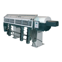
Step 4: Remove the two scissor support pieces by loosening the 6mm bolts. (The scissor support pieces are located by the front
rest)
Scissor
support piece
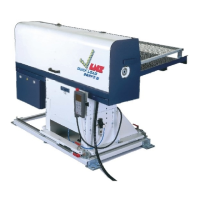
Step 5: Rotate the scissor support pieces 180° and install them back onto the scissor support arms and tighten the 3mm bolts.
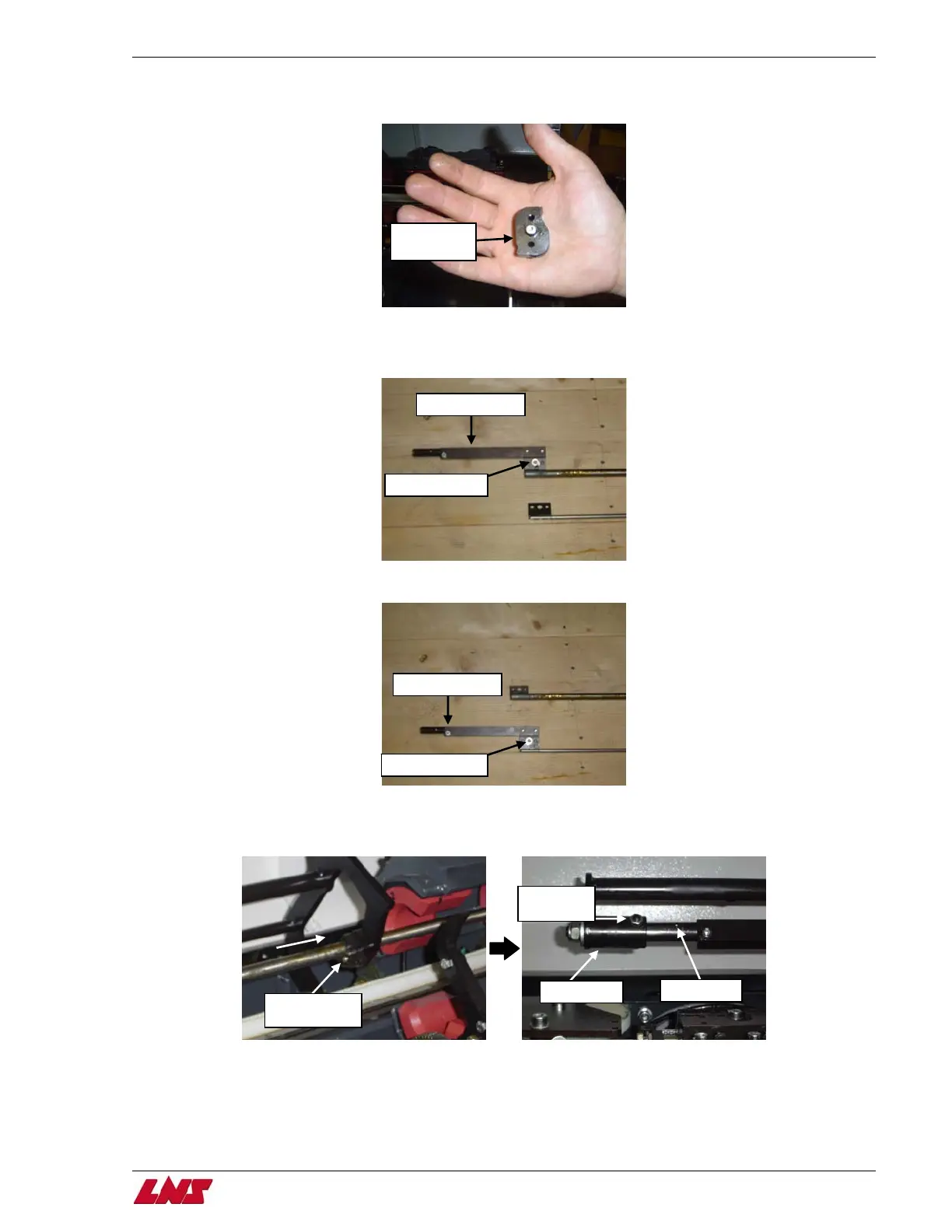
Step 6: Loosen the 6mm bolt on the pusher flag and remove the pusher connector from the pusher.
Pusher connector
Loosen 6mm bolt
Step 7: Attach the new pusher and the pusher connector together and tighten the 6mm bolt.
Pusher connector
Tighten 6mm bolt
Step 8: Gently slide the pusher through the pusher support bushing and insert the pusher connector into the rear support. When
inserting the pusher connector into the support, make sure that the countersink on the pusher connector is lined up with the
ball detent set screw on the rear support.
Ball detent
set screw
Rear support
Pusher support
bushin
Countersink
Procedure complete.