Chapter 3: Procedures
QUICK SIX
3-13
SQ1 Adjustment – Measuring Cell
This procedure is used to adjust the measuring cell switch.
Tools List:
• Small screw driver
• Two 7mm open end wrench
Procedure
Conditions:
• Main bar feed power on
• Main guiding channels open
• Smallest diameter guiding elements available (bottom blocks only)
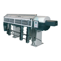
Step 1: Place the bar stock in the guiding channel.
Step 2: Run the bar stock forward by hand.
Step 3: Check the vertical alignment of the sensing beam on the material. The beam should be centered on the bar stock. If the
beam is not centered on the bar stock, loosen the two 7mm bolts and adjust the sensor so that it is centered. Retighten the
bolts when the sensor is adjusted correctly.
Loosen both
7mm
l
SQ1
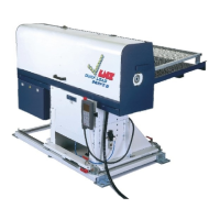
Step 4: With a small screw driver, turn the yellow screw counter-clockwise to its limit.
Rotate yellow screw
counte
-clockwise
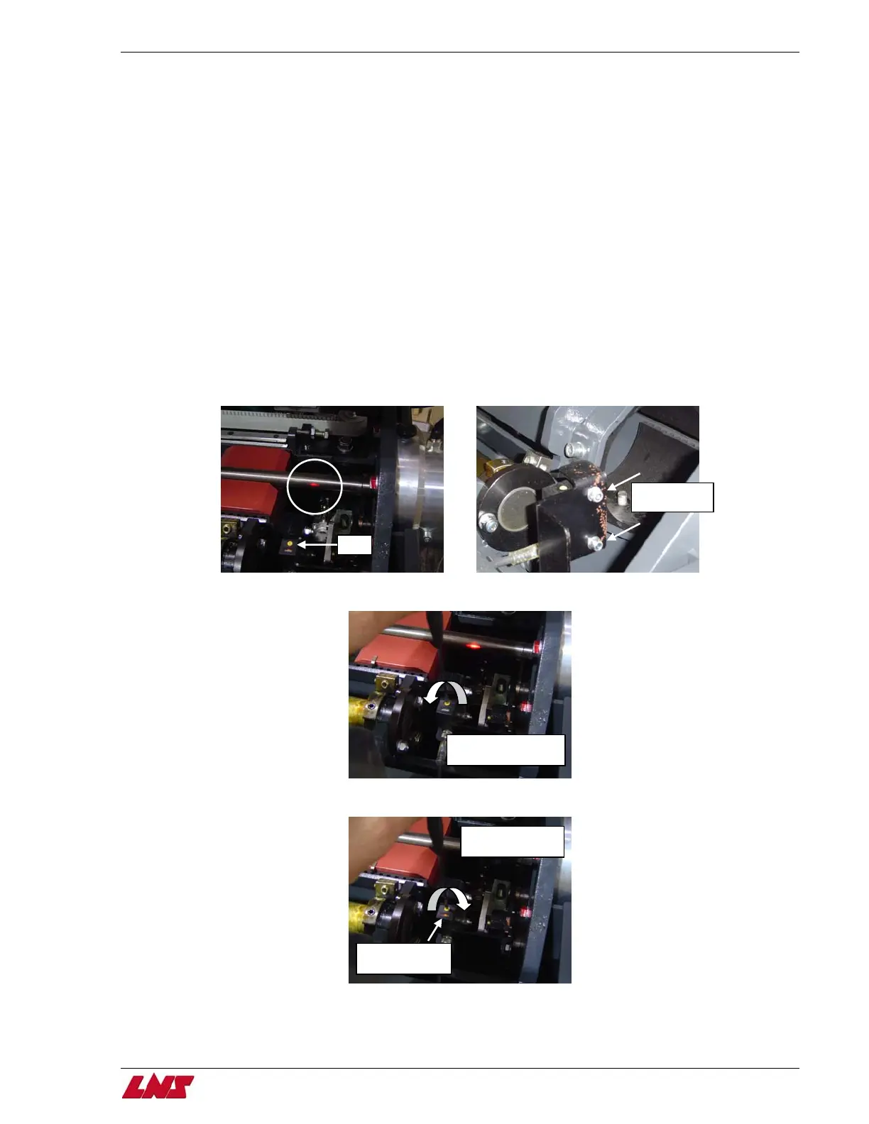
Step 5: Using the small screw driver, turn the yellow screw clockwise until the LED light illuminates.
Rotate yellow
screw clockwise
Turn until LED
li
ht illuminates
Step 6: From the point when the LED light first illuminates, turn the yellow screw one full clockwise revolution.
Procedure complete.