6
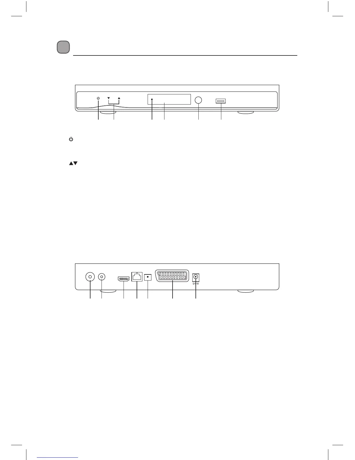
Rear View
Product Overview
Front View
1 2 43 5 6
1. Button
• Switches the unit between the ON
and STANDBY modes.
2. Button
• To change channels.
3. Power indicator
• Lights up red when the unit is in
STANDBY mode.
• Lights up green when the unit is on.
4. LED Display
• Display is blank when in standby
mode.
• Displays the current programme
number after the unit is turned on.
5. Remote Control Sensor
6. USB Socket
HDMI OUTPUT ETHERNET OPTICAL
AUDIO OUT
SCART (TV)
DC IN
ANTENNA IN ANTENNA OUT
1. Aerial IN Socket
2. Aerial OUT Socket
3. HDMI Socket
4. Ethernet Socket
5. OPTICAL Socket
6. SCART TV Socket
7. DC IN Socket
1 2 3 4 5 6 7
L1HSTB12_IB_120725_CS4_Edits_Pauline.indd 6 30/07/2012 14:57
 Loading...