Introduction 9
1. Introduction
1.1 Overview
The GS550 system includes the cabin mounted GS550 radio display and compatible crane
mounted sensors. The GS550 creates a two-way radio network with the sensors to bring required
lift data to the operator. Hoist load, boom and jib angles, boom length, wind speed and pending
two-block can be detected and indicated to the operator in real time. Working load radius can be
calculated and compared to a rated capacity chart (if programmed). Furthermore the GS550 can
be programmed to generate warnings, alarms and lockout commands, all triggered by adjustable
thresholds and limits. All these events can be recorded by the data logger with a time and date
stamp. The exact operational function of the GS550 system depends on the sensor configuration
used and the rated capacity charts programmed (where applicable). The GS550 includes an
infrared port to facilitate software and chart updates and data logger downloads using a compatible
personal digital assistant (PDA) or cell phone. Compatible sensors include the GS050 anti-two-
block, the GC series load cells and GS001 series line rider and load pin transmitters, the GS010
angle sensors, the GS011 angle sensor and length transmitter and the GS020 wind speed sensor.
The GS550 system is designed as an operator aide and is in no way a substitute for safe operating
practice
1.2 Version Compatibility (applies for produced manufactured prior to
June 2007)
GS series product with version 2 firmware is not compatible with GS series product with version 1
firmware. For information on upgrading GS series product from version 1 to version 2 firmwares
please contact LSI.
1.3 Start-Up
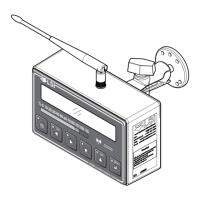
The GS550 (see Figure 1) must be correctly programmed for the system sensors installed. The
GS550 powers up with several green lights flashing, this indicates that the display is waking up
programmed sensors and creating a radio communication link with each. Once a reliable radio
communication network is established, all green lights will remain lit without flashing.
This process may take up to one minute. The delay is created by the battery management function
and does not affect system security. If an anti-two-block switch detects a pending two-block event,
if a load cell detects a change in load, or if an angle sensor detects a change in angle, the appro-
priate radio link will be established in less than 0.1 seconds. To immediately wake-up a load cell,
lift the hook with a load; to immediately wake up an angle sensor, change the boom angle.
In special conditions of lockout created by a missing sensor, you may press the BYPASS button to
allow the system to work. When rigging the crane, out of normal capacity chart condition could
create annoying alarms, and the display could then be put in ‘rigging mode’. If the rig mode is
enabled in the display, press BYPASS for 10 seconds to activate it. If the rig mode is not available,
contact your LSI representative or LSI technical support (p. 75).

 Loading...