2. Operation 41
2.10 Rope Payout
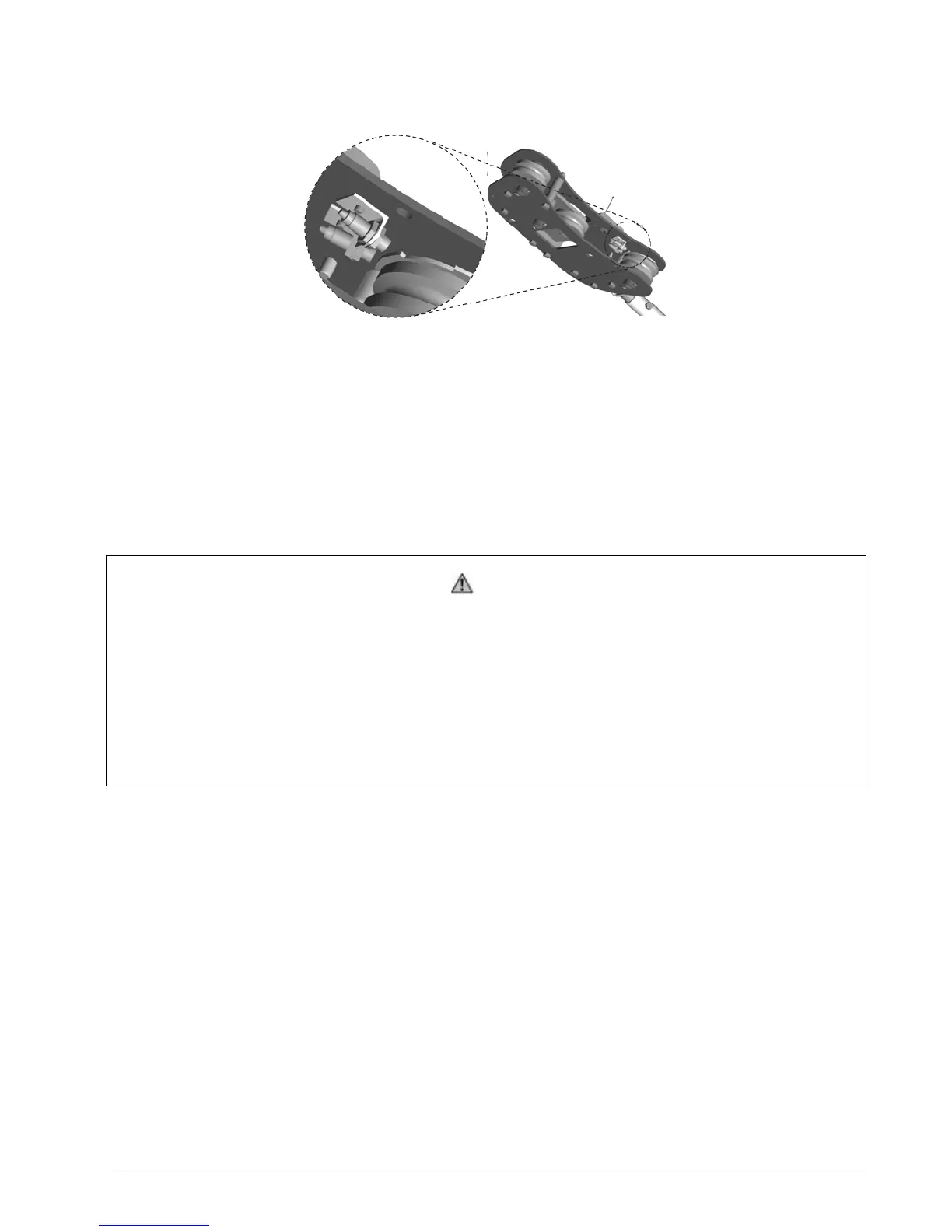
Figure 21 Rope Payout Display
Typically the rope payout sensor is factory installed on the line rider load sensor (see Figure 21).
Alternatively the rope payout sensor may be installed on an appropriate sheave. Power supply
must be provided to the rope payout sensor. A GS550 display can then be programmed to com-
municate with the sensor and to indicate rope payout (length) and rope speed.
Zero the rope payout using the Tare menu before calibration.
2.10.1 Rope Payout Initialization
Warning!
Before you calibrate the system, ensure to initialize the rope payout for the following
reasons:
1. When you receive a Rope Payout system, the system should be reset to 0 to en-
sure it starts with the 0 position.
2. When you have already the GS550 display, the Rope Payout system should be
reset to 0 because the display keeps into memory values, and the memory value
requires an update or a reset to 0.
To set the zero position of the rope payout, follow these steps:
1. On the display, press the Tare button.
2. Select the Rope Payout sensor.
3. Press the Enter button.
The display will show “New rope payout zero saved in sensor”.
4. Press the Exit button.
This concludes the rope payout initialization procedure.
2.10.2 Rope Payout Calibration Procedure № 1: Mechanical Set-Up
1. Hoist up to reel in the wire rope fully.
2. Install the rope payout system.
3. Zero the rope payout length in the Tare menu
4. Hoist down to pay out a known length of wire rope (for example: 20 feet).

 Loading...


