34 The GS550 System
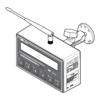
2.6.6 Load Pin Transmitter GS001
1. Determine the transmitter mounting position (see Figure 17).
a. The load pin and transmitter pigtails must connect easily without stretching or kinking
at all boom angles and working conditions. The jumper cable may be used between
the load pin and transmitter to increase transmitter placement options.
b. There must be direct unobstructed line of sight from the transmitter to the display; this
may not be required on cranes with a maximum boom length less than 100 feet (33
metres).
c. The transmitter antenna must not be in contact with any metal object.
Warning!
Do not weld in proximity to LSI sensor/transmitters.
2. Weld the mounting blocks where required.
3. Mount the load pin transmitter on the mounting blocks.
2.7 Load Pins, Line Riders and Compression Cells: Calibration
Load pins, line riders and compression cells must be calibrated at installation and every time
thereafter the installation, the load sensor or the load transmitter is changed.
Important!
Do not recalibrate flat bar load links (part numbers GC005, GC012, GC018, GC035, GC060,
GC100, and GC170).
This procedure requires two known weights. The first (light) weight should be about 10% of load
sensor capacity and not less than 5%. The second (heavy) weight should be over 50% of capacity,
and absolutely not less than 25%.

 Loading...