2. Operation 39
2.9.2 Mounting Instructions
Warning!
Remove the angle sensor from any connecting metal structures or surfaces when welding
the metal lugs to the mounting surface. Proximity to welding may cause permanent dam-
age to the angle sensor and prevent accurate angle indication.
1. Determine the angle sensor position.
a. The mounting surface must be flat and known to be level (0°) in both the list and trim
axes.
b. The angle sensor must have a clear line of sight to the cabin mounted display.
c. The angle sensor must be installed horizontally, with the antenna pointing up.
d. The list and trim axes are indicated on the angle sensor, follow these indications to ori-
ent the sensor correctly for accurate list and trim indication.
e. The angle sensor antenna must not contact a metal object.
2. Install the welding pads; keep the angle sensor well removed from the weld site and any
connecting metal objects while welding.
3. Mount the angle sensor to the weld pads with the screws and washers provided.
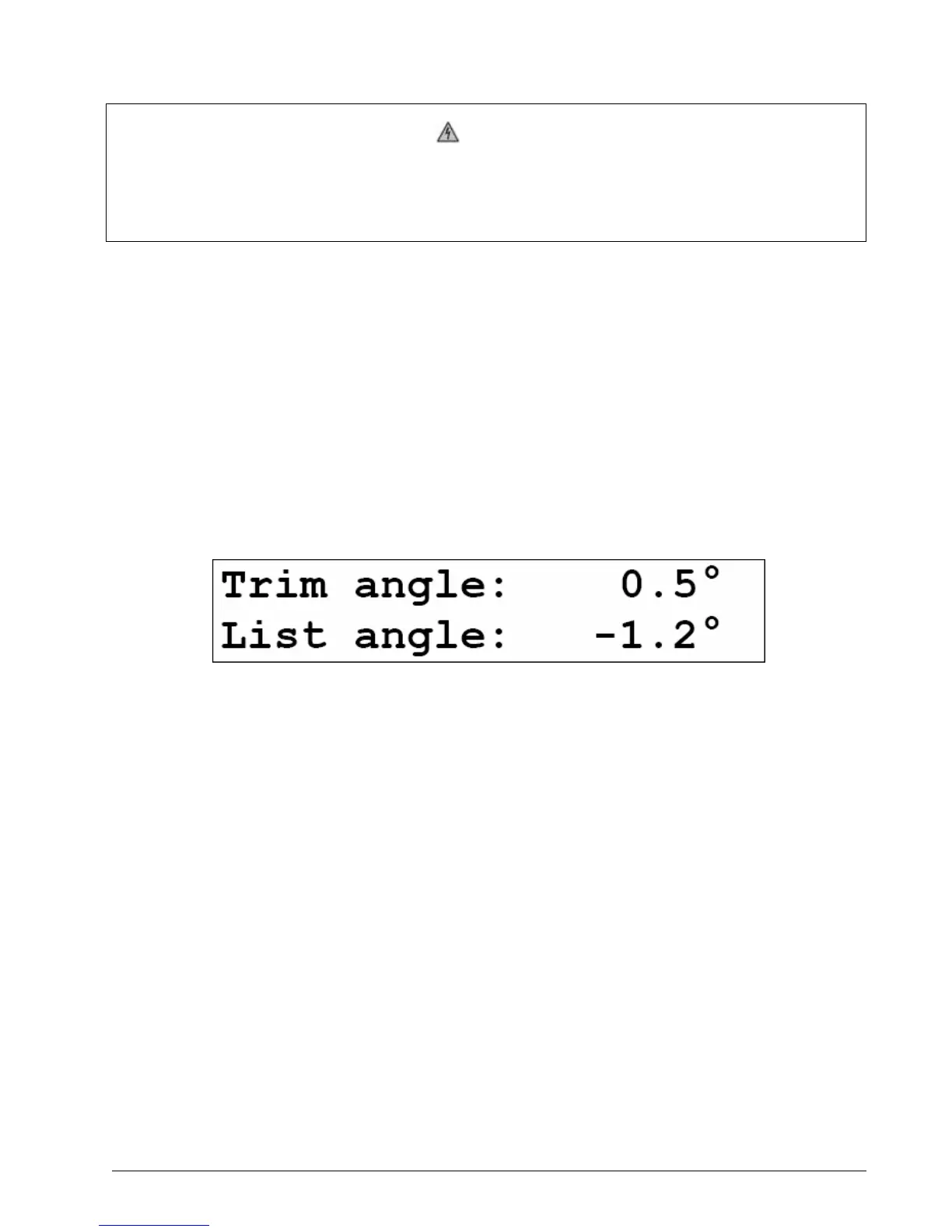
4. Verify list and trim angle indication by the GS550 (see Figure 19); in operation display, use
Next to advance to the list and trim indication page.
Figure 19 Trim And List Angle Indication
2.9.3 List and Trim Angle Calibration Procedure
Calibrate angle indication by adjusting the offset values for list and trim in the GS550 display; the
GS550 will then communicate the updated offset values to the sensor.
1. Install the sensor at a precisely known list and trim angle.
2. Press Menu, and then Next three times to go to 4) Installation.
3. Press Enter and Next to go to 4B) Sensor Calibration.
4. Press Enter to go to the password page.
5. Use Back, Next, Up and Down to enter the user password, and then press Enter to go to 4B1)
Automatic value calibration wizard.
6. Press Enter to go to page 4B1A)
7. Use Back and Next to select the trim (or list) sensor.
8. Press Enter twice to go to the first step of the calibration wizard; note the uncorrected angle
indicated.
9. Press Next to go to the second step, angle correction. Use Up and Down to adjust the angle
value indicated until it is equal to the known angle.
10. Press Next to go to the third step, note the offset value.

 Loading...


