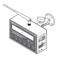
14 The GS550 System
Info. When the orange Info light flashes press Info to see critical system
alerts. Press Next to advance from one page to the next.
Standard info menu pages include:
• BIOS (Binary Input Output System) number and version
• Firmware number and version
• Chart number and version (if available)
• SPKG (Software Package) number
Alert
Description
The sensor indicates a value greater than the operator adjusted limit
Warning!
Do not operate the crane beyond the limits specified by the
manufacturer.
• Verify operator adjusted limits in the limit menu.
The sensor indicates a value less than the operator adjusted limit
Warning!
Do not operate the crane beyond the limits specified by the
manufacturer.
• Verify operator adjusted limits in the limit menu.
Less than 10% of battery life remains in the sensor.
• Schedule battery replacement for the next available opportunity. Typically
several weeks of operation remain from the moment the sensor low battery
warning is first triggered.
The display isn’t receiving communication from the sensor.
• Verify that the sensor id number programmed matches the id number of the
sensor installed on the crane. Go to menu 5A1.
Voltage is detected on the lockout wire when in alarm
*
. With the standard relay
configuration voltage should not be present on a lockout wire in alarm condition.
• Verify the wire connection. Refer to the Power Supply and Wire Connection
sub section of the Installation Manual.
Voltage is not detected on the lockout wire when safe
†
. With the standard relay
configuration voltage should be present on a lockout wire in safe condition.
• Verify the wire is not shorted to ground.
• Verify the wire is not connected directly to the valve coils; a relay should be
installed between the wire and the valve coils. Refer to the Power Supply and
Wire Connection sub section of the Installation Manual.
One or more primary conditions of the chart selected for the hoist is not met
(example: telescopic boom length).
• Verify the conditions of the selected rated capacity chart.
*
If the lockout relay is inverted this alert will occur when voltage is detected on the wire when safe.
†
If the lockout relay is inverted this alert will occur when voltage is not detected on the wire in alarm.

 Loading...