Lucent Technologies -48V CPS4000/CPS4000 PLUS Cabinet Power System
Issue 13 December 2000 Installation and Testing 5 - 25
Initial Start-up and Test, continued
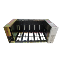
Power Units
Power Units
Step Action
1
Turn the ac service circuit breakers On.
2
Seat each rectifier and/or converter using the 3/16-inch Allen
wrench, turning the mounting screw clockwise. Verify that the
fan operates on the rectifier or converter.
Note: In order to verify fan operation, it may be necessary to
have only one rectifier or converter seated and operating at a
time.
3
After all the rectifiers and/or converters are seated, verify that
the yellow Standby LED lights on all of them.
4
Turn one rectifier or converter On. As the rectifier is turned On,
verify:
• LVD Fail LED lights momentarily on the BSP2 or BSP2C
distribution unit (occurs with the first rectifier only)
5
Place a test load across TB1 (+) and TB3 (-) located in the bulk
distribution module for the primary bus output on the initial
shelf or TB1 (+) and TB2 (-) for the primary bus output on the
supplemental shelf. Set the test load to approximately 2
amperes. This test verifies that the rectifier(s) will support a
load.
6
Place a test load across J14 pins 4 through 9 (+) and J14 pins 10
through 15 (-) for the secondary output. Set the test load to
approximately 2 amperes if ES680 or ES681 converters are
installed.
7
Turn all remaining rectifiers and/or converters On using the On/
Standby switches. Verify that the yellow Standby LEDs
extinguish and the green On LED lights on all power units.
8
Verify that the green Normal LED on the control unit lights and
all Alarm LEDs extinguish after all rectifier switches are in the
On position.