Lucent Technologies -48V CPS4000/CPS4000 PLUS Cabinet Power System
5 - 2 Installation and Testing Issue 13 December 2000
Preparation, continued
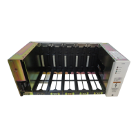
Wiring Guidelines • The commercial ac power input wiring enters the plant on the left
(or rear on List 25R or 25RB only). The plant output wiring exits
the plant on the right. The alarm wiring to general office alarms
exits the plant on the left. The inter-shelf signal connector is located
on the left. Loads and batteries are connected to the power shelves
at the output buses of the CPS shelf on the right side.With the
remote access option, the communication connections exit from the
left-side access slot in the control unit faceplate.
• All electrical connections should be made using the proper
crimping tools and dies and should be torqued to values specified
on the product labels and in Tables 3-F and 3-H.
• All building wiring should comply with the NEC and other
applicable local codes. The temperature rating of the wire must be
no less than 90° Celsius and should be sized using the 60° Celsius
ampacity table in the NEC handbook. Wiring internal to enclosed
equipment cabinets must be rated no less than 105° Celsius.
DANGER
Only qualified personnel should install and service the CPS
shelf and plug-in modules. Hazardous energy and voltages are
present in the unit and on the interface cables and will shock
or cause serious injury or death if safety precautions are
ignored. Follow all safety warnings and practices when
servicing this equipment.