363-206-295
Power
4-4 Issue 1 December 1997
LEDs 4
Two green power on (PWR ON A and PWR ON B) LEDs on the Group 4 shelf
user panel indicates that the shelf is receiving fused −48 volt power. The LEDs will
remain illuminated as long as either −48 volt feeder is supplying power to the
shelf.
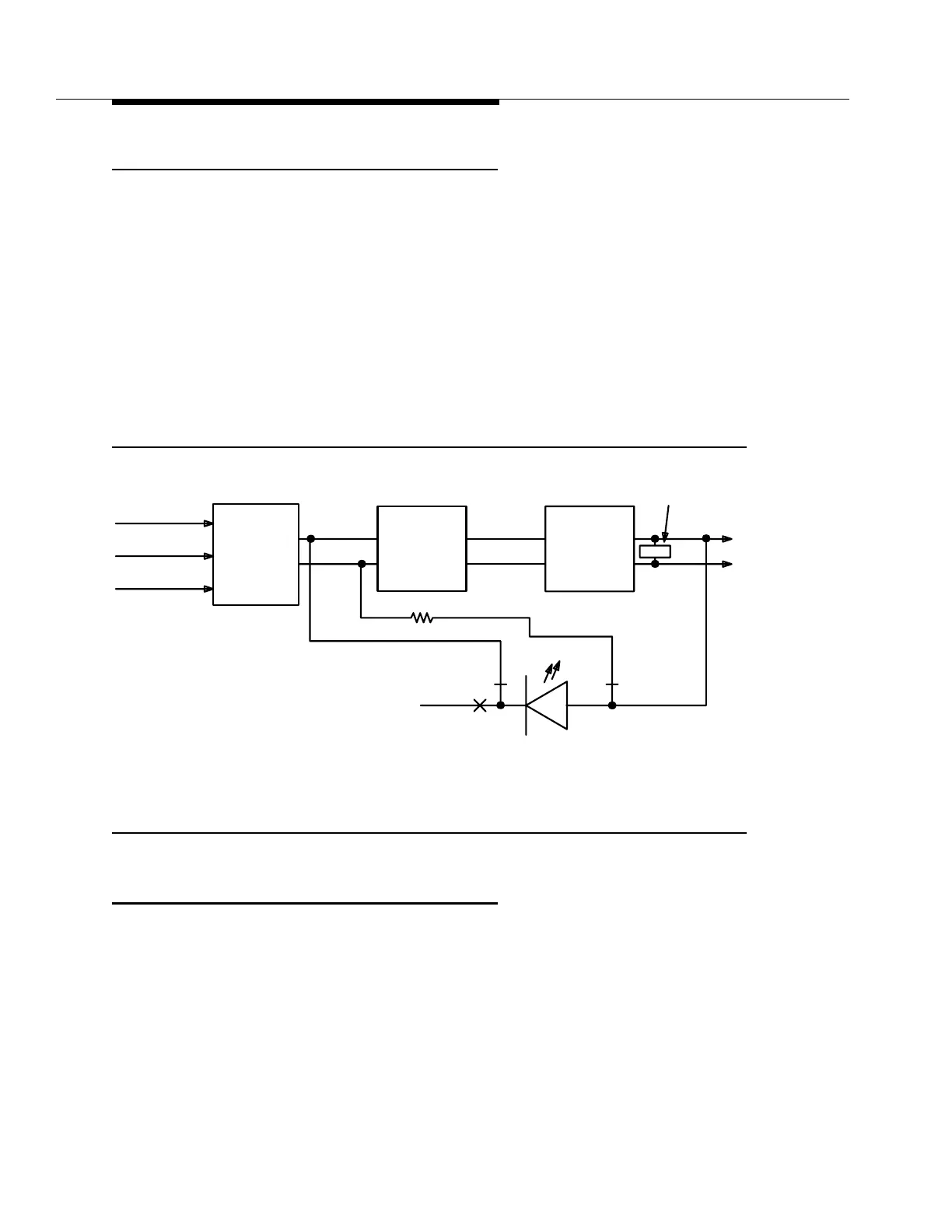
Normally the FAULT LED on the circuit pack faceplates is operated via the
controller which provides a ground return for current generated by the on-board
converter. In the event of a DC-to-DC converter failure, the LED will be operated
via the −48 volt power leads. The −48 volt power leads are supplied through an
electronic gate or relay contact normally held open by the converter. The power,
fusing, and LED circuits shown in Figure 4-2 are used on all circuit packs with on-
board DC-to-DC converters.
Figure 4-2. Circuit Pack Power and LED Control
Power Minor Alarm 4
A yellow power minor (PMN) alarm LED is provided on the user panel to indicate
an AC power failure at the remote terminal. The PMN alarm can be provisioned by
a switch on the SYSCTL circuit pack at the central office (CO) to be either an
office minor (MN) or office major (MJ) alarm.
-48 V (A)
RTN
&
+5 V
Relay
Converter
GND
DC/DC
-48 V-48 V
-48 V (B)
(Red)
&
Fault LED
LED Control
Filtering
Fuse
Limiter
Current
ORing
Diode
RTNRTN