363-206-295
Transmission and Synchronization Interfaces
Issue 1 December 1997 5-27
Synchronization Reconfiguration in an Access Ring 5
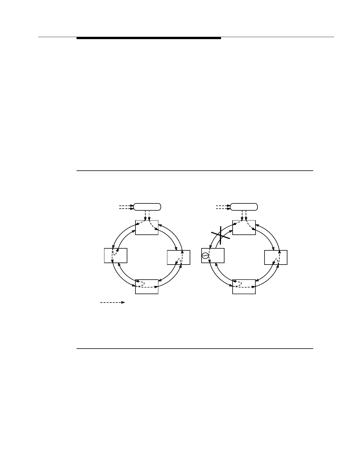
Figure 5-10a shows the access ring operating in its normal configuration. The
DDM-2000 Multiplexer at the CO is externally timed, and each of the other
DDM-2000 Multiplexers are line timed in a counterclockwise direction. The SQU
message is sent to indicate where timing is traceable to an external BITS and
where it is valid to be used. The timing looped back (TLB) message is sent on the
interface that is being used as the line-timing reference because a timing loop
would be created if this timing reference were used. Synchronization messaging
and automatic synchronization have both been enabled for this network.
In Figure 5-10b, a fiber has been cut between sites A and B. Immediately, the
DDM-2000 Multiplexer at site B enters holdover and sends out the internal clock
(IC) message to site C. The DDM-2000 Multiplexer at site B cannot switch to line
time from site C because it is receiving the TLB message on that interface.
Figure 5-10. Synchronization Reconfiguration — Access Ring (Sheet 1 of 3)
PRS
Traceable
BITS
DDM-2000
DDM-2000
DDM-2000
PRS
Traceable
BITS
Sync Flow
a) Before Failure
SQU
Site A
Site D
Site B
Site C
SQU
SQU
SQU
TLB
TLB
TLB
SQU
DDM-2000
DDM-2000
SQU
Site A
Site D
Site B
Site C
SQU
SQU
TLB
TLB
SQU
b) Failure Occurs,
Site B Changes Message
DDM-2000
DDM-2000
DDM-2000
STRATUM 3 if using a TG3 at site B, or IC if using a TGS.
IC
*
*