363-206-295
Transmission and Synchronization Interfaces
5-28 Issue 1 December 1997
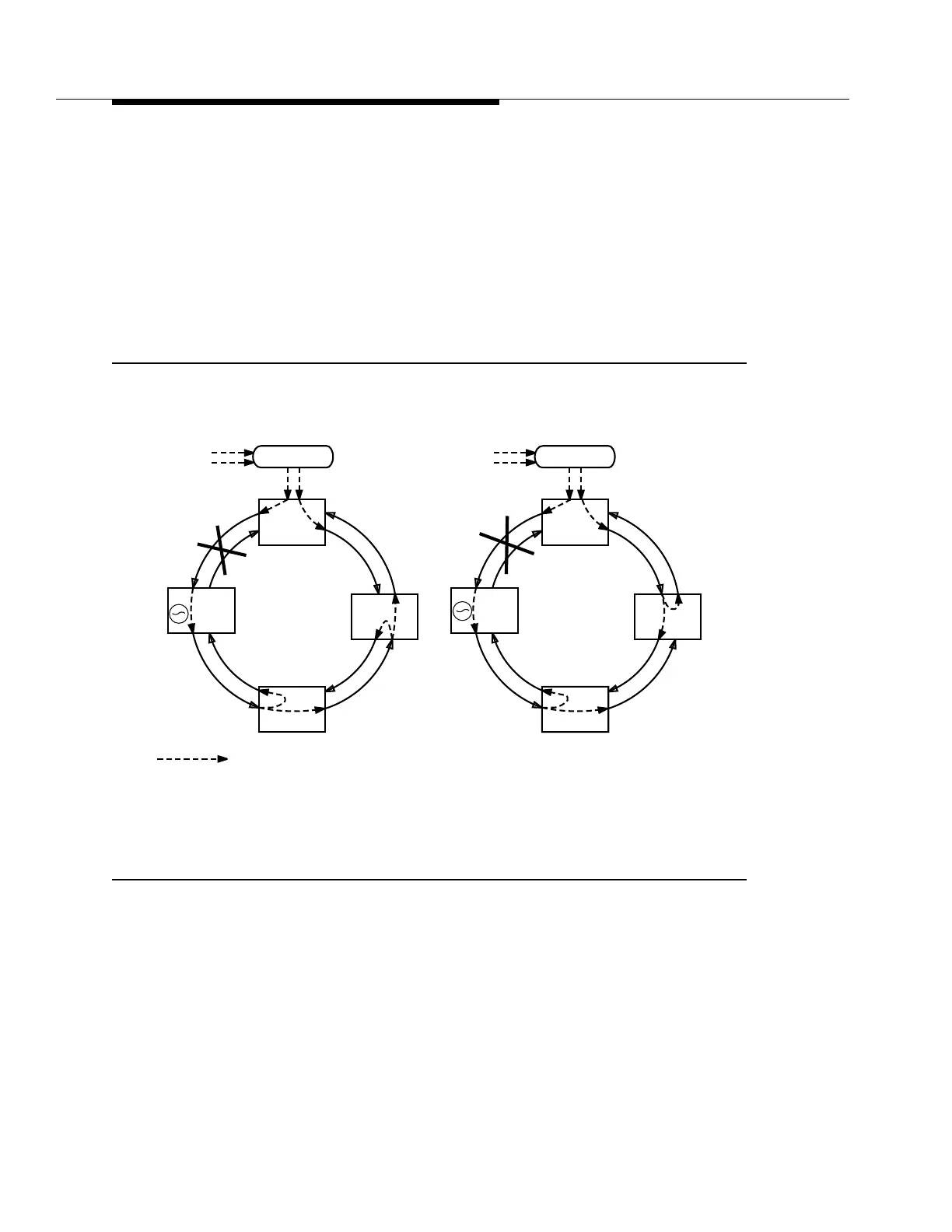
In Figure 5-10c, the DDM-2000 Multiplexer at site C detects the incoming IC
message and sends out the IC message to site D. The DDM-2000 Multiplexer at
site C cannot switch to line time from the other rotation because it is receiving the
TLB message on that interface and continues to derive timing from Site B.
In Figure 5-10d, the DDM-2000 Multiplexer at site D detects the incoming IC
message. Because this DDM-2000 Multiplexer is receiving the SQU message
from site A, it will switch to line time from site A because SQU is higher quality
than IC. After the switch occurs, the TLB message is sent back to site A and the
SQU message is retransmitted to site C.
Figure 5-10. Synchronization Reconfiguration — Access Ring (Sheet 2 of 3)
PRS
Traceable
BITS
DDM-2000
DDM-2000
DDM-2000
PRS
Traceable
BITS
Sync Flow
SQU
Site A
Site D
Site B
Site C
SQU
TLB
TLB
SQU
DDM-2000
DDM-2000
SQU
Site A
Site D
Site B
Site C
SQU
TLB
SQU
c) Site C Changes Message
d) Site D Reconfigures
IC
IC
TLB
IC
DDM-2000
DDM-2000
DDM-2000
IC
STRATUM 3 if using a TG3 at Site B, or IC if using a TGS.
*
*
IC
*