ELECTRIC SYSTEM 18000 SERIVCE/MAINTENANCE MANUAL
3-12
Published 12-05-17, Control # 035-23
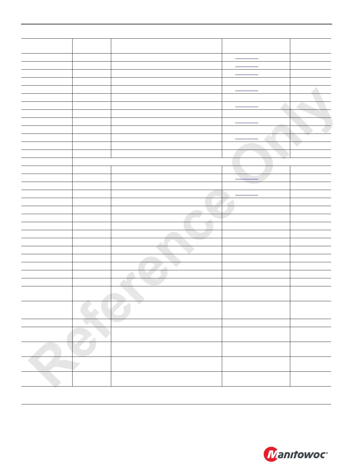
34-P DO-16 Drum 2 Pump Control – Raise See Table 3-3 for Values CAN33-2-128
34-R DO-15 Drum 2 Pump Control – Lower See Table 3-3
for Values CAN33-2-64
34-S DO-18 Drum 1/3 (opt.) Pump Control – Lower See Table 3-3
for Values CAN33-3-2
34-T Ground Left Track Pump Control – Forward Ground
34-U DO-19 Left Track Pump Control – Forward See Table 3-3
for Values CAN33-3-4
34-V Ground Left Track Pump Control – Reverse Ground
34-W DO-20 Left Track Pump Control – Reverse See Table 3-3
for Values CAN33-3-8
34-X Ground Swing 1 Pump Control – Left Ground
34-Z DO-21 Swing 1 Pump Control – Left See Table 3-3
for Values CAN33-3-16
34-a Ground Swing 1 Pump Control – Right Ground
34-b DO-22 Swing 1 Pump Control – Right See Table 3-3
for Values CAN33-3-32
34-g Ground Jumper to Node Select 2 0 Volts (With Jumper)
34-j NS-2 Node Select Jumper to Ground 0 Volts (With Jumper)
J6 Receptacle – Drum 3 Controls
36-A Ground Drum 3 Motor Control Ground
36-B DO-7 Drum 3 Motor Control See Table 3-3
for Values CAN33-1-64
36-C Ground Drum 3 Brake Solenoid Ground
36-D DO-8 Drum 3 Brake Solenoid See Table 3-3
for Values CAN33-1-128
36-E Ground Pump Drive Cooler Pressure Ground
36-F DO-9 Pump Drive Cooler Pressure 0 Volts Off; 24 Volts On CAN33-2-1
36-G Ground Drum 3 Minimum Bail Limit Switch Ground
36-H DO-10 Drum 3 Minimum Bail Limit Switch 0 Volts Off; 24 Volts On CAN33-2-2
36-J DI-8 Drum 3 Minimum Bail Limit Switch 0 Volts Off; 24 Volts On CAN59-1-128
36-L NS-2 Node Select 2 Jumper to Ground 0 Volts (With Jumper)
36-U Ground Jumper to Node Select Ground
36-V 5 Volts Drum 3 and 5 Motor Speed Sensor 0 to 5 Volts
36-W Ground Pump Drive Temperature Sender Ground
36-X 28 Volts Pump Drive Temperature Sender 28 Volts Nominal
36-Z Ground Drum 5 Motor Speed Sensor Ground
36-a AI-9 Pump Drive Cooler Pressure
1 Volt at 0 psi;
5 Volts at 200 psi
CAN6-2
1
36-b AI-10 Pump Drive Temperature Sender
32.5K ohms at 0
o
C;
680 ohms at 90
o
C
CAN6-4
1
36-j Ground Drum 3 Motor Speed Sensor Ground
36-n ENC-1A Drum 3 Motor Speed Sensor
1.2 or 3.2 Volts Not
Moving; 2.2 Volts Moving
CAN58-2
2
36-p ENC-1B Drum 3 Motor Speed Sensor
1.2 or 3.2 Volts Not
Moving; 2.2 Volts Moving
CAN58-2
2
36-r ENC-2A Drum 5 Motor Speed Sensor
1.2 or 3.2 Volts Not
Moving; 2.2 Volts Moving
CAN58-4
2
36-s ENC-2B Drum 5 Motor Speed Sensor
1.2 or 3.2 Volts Not
Moving; 2.2 Volts Moving
CAN58-4
2
1
– Lower four bits are the most significant bit of the analog value.
2
– The number in the indicated bank should increase with device rotation and decrease with rotation in opposite direction.
Can ID. No.
Function
Type
Description Test Voltage Packet No.
 Loading...


