1
S/N
W*3W*4
WN
OUT
WN
IN
W*6
MCC A01411
CONTROLLER
UNIVERSAL NODE
A00323
P2066
P2065
P2071
1
15
14
17
16
19
13
18
6
0
7
3
2
In Right Side
Cab Console
10
On Boom Top
8
5
9
In Boom Butt
4
11
On Jib Top
18CSM10-101
18CSM3-101
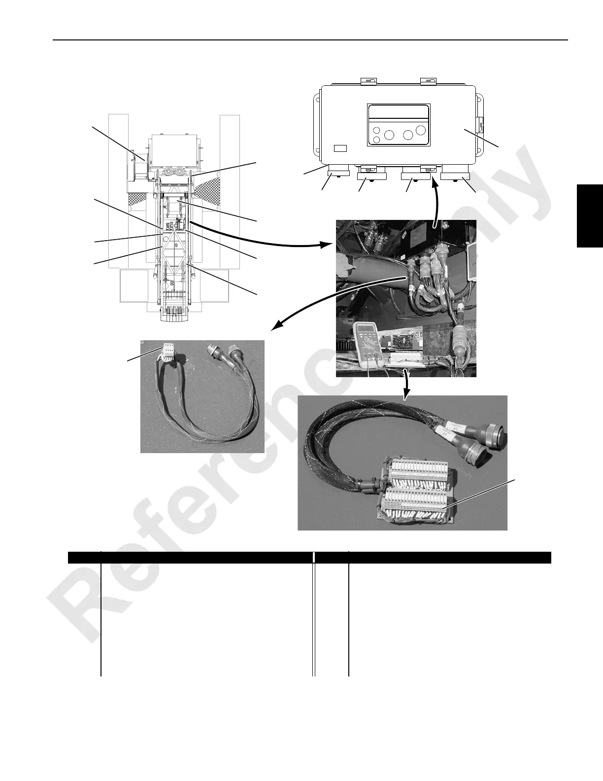
Item Description Item Description
0 Node-0 Engine Node 10 Node-20 At Boom Top
1 Node-1 Master Node in Front Console 11 Node-21 At Jib Top
2 Node-2 In Right Side Console 12 Universal Node Controller (3 through 9)
3 Node-3 Left Side of Crane in Machinery Enclosure 13 Node In-line Test Board (3 Separate Boards)
4 Node-4 Left Side of Crane in Machinery Enclosure 14 W4 Connector - 110 Degree Key
5 Node-5 Right Side of Crane in Machinery Enclosure 15 W3 Connector - Zero Degree Key
6 Node-6 Right Front Side of Rotating Bed 16 W6 Connector - 80 Degree Key
7 Node-7 In Swivel Area 17 J1 Connector - Communication In
8 Node-8 In Boom Butt 18 J7 Connector - Communication Out
9 Node-9 MAX-ER At Rear of Rotating Bed 19 Communication In-line Test Board (1 Board)
FIGURE 3-2
 Loading...


