HOISTS 18000 SERIVCE/MAINTENANCE MANUAL
5-20
Published 12-05-17, Control # 035-23
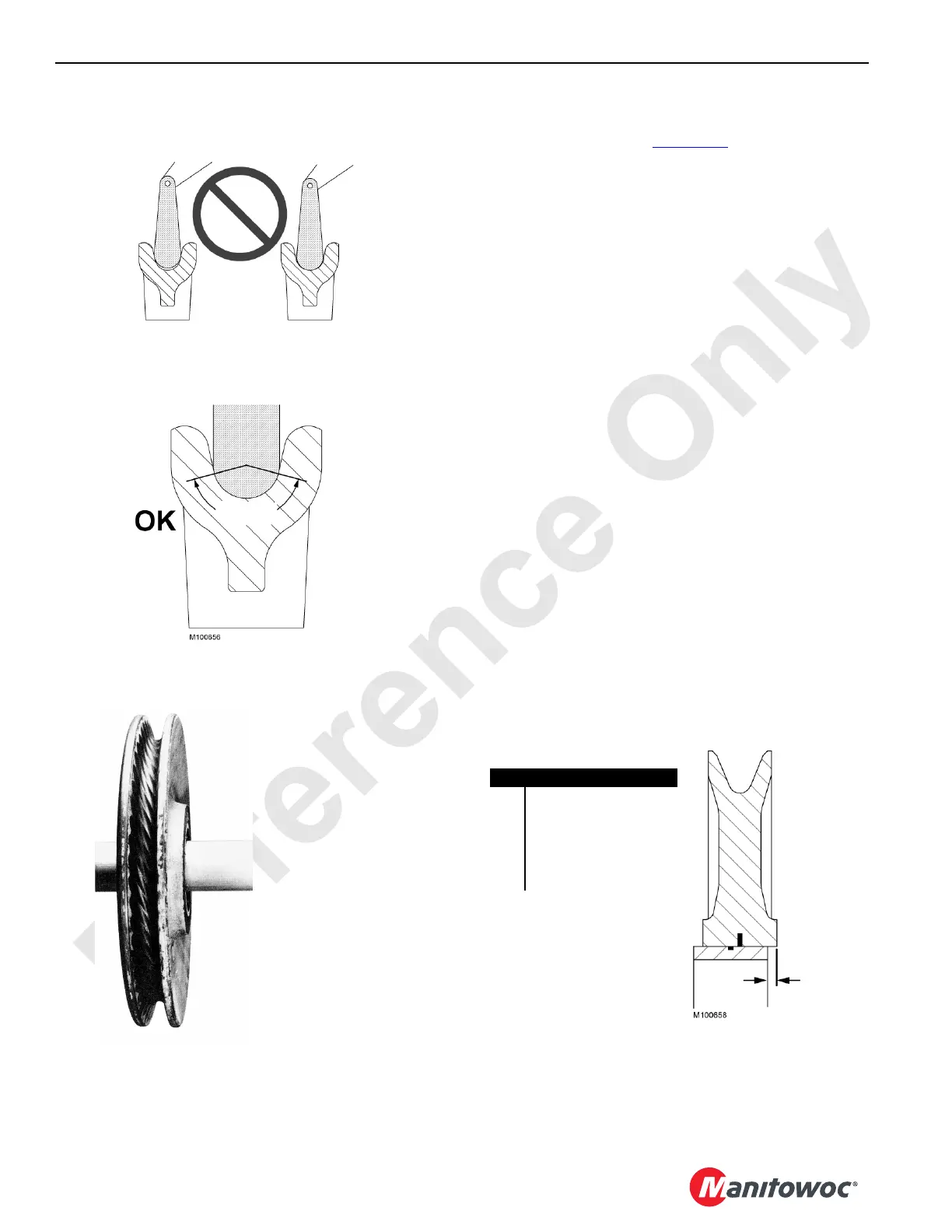
8. Inspect the nylon sheaves to verify they have not
separated and “walked off” the steel inserts or the
bearings as shown in Figure 5-17
. Maximum sideways
displacement is 3 mm (1/8 in.). Replace worn or
damaged sheaves.
NOTE: Depending on the type of wire rope used, it is
normal for nylon sheaves to show the wire rope
print. Do not machine the nylon sheaves.
NOTE: Nylon sheaves cannot be accurately inspected
using conventional methods such as sheave
gauges.
Due to the characteristics of nylon sheaves, the
nylon material will actually move to better support
the wire rope as the sheave wears normally.
Nylon sheave properties will be degraded in
temperatures above 60° C (140°F).
NOTE: Many current production sheaves are not equipped
with grease fittings, but are packed with grease at
assembly. Repack the bearings of these sheaves
with CraneLUBE EP #2 grease when the sheaves
are overhauled.
Due to application and design variations, it is not
possible to give specific grease repacking intervals
or the life expectancy of the components.
9. Make sure the sheaves, drums, and rollers are properly
lubricated according to the instructions in the lubrication
guide provided with this manual.
NOTE: For some sheaves, the seals are an integral part of
the bearing. Therefore, if a seal is damaged during
repacking, the complete bearing may have to be
replaced.
Observe the groove to see if the contour of the gauge
matches the contour at the bottom of the sheave groove.
Proper fitting sheave groove should support
the
wire rope or 135–150° of rope circumference.
Groove Too Small
Groove Too Large
135°–150°
FIGURE 5-15
“Corrugated” steel sheave,
roller, or drum will cause the
wire rope to wear rapidly.
FIGURE 5-16
Item Description
1 Nylon Sheave
2 Improper Snap Ring
Engagement
3 Steel Insert of Bearing
4 1/8 in (3 mm) Maximum
Sideways Displacement
FIGURE 5-17
 Loading...


