Manitowoc Published 12-05-17, Control # 035-23 1-51
18000 SERIVCE/MAINTENANCE MANUAL INTRODUCTION
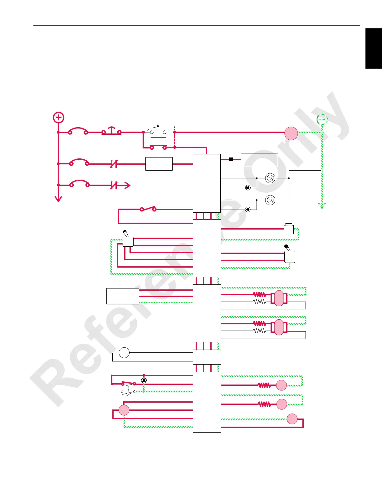
When drum control handle is moved to neutral position,
node-1 controller compensates for hydraulic system leakage
or changing engine speed. Node-3 controller sends a zero
output voltage to each pump EDC that moves swashplate to
center position. This shifts the motor back to maximum
displacement for slower output speed to slow the drum
rotation. Node-1 controller stores the load holding pressure
in pressure memory.
After control handle center switch opens, node-6 controller
sends a zero output voltage to disable drum brake solenoid
valve HS-10. Drum brake solenoid valve shifts to block pilot
pressure to brakes and opens a line to tank. Brakes apply
before drum pump de-strokes.
The diverting valve lines to main hoist 2/5 drum motor remain
open until mast hoist control handle is selected for operating
mast hoist in Setup mode.
0
CRANE DISPLAY
10 AMP
6C8
6A
CB4
ENGINE
STOP
6C8A
P12-24
P12-14
SYSTEM FAULT
ALARM
P11-07
P11-09
OPERATING LIMIT
LIGHT
GND
START
STOP
ENGINE
RUN
3
7
X
24 VOLTS
ALARM
LIGHT
CAB
PWR
50 AMP
CB7
6C13
CAN POWER
8C
WCP
P12-37
P12-38
CB8
NODE 0
NODE 1
(Master)
ROTATION
P22-02 (W1P52-02)
DRUM 2
W66-F
W66-E
HANDLE
P22-24 (W1P52-24)
BRAKE
GND
DO
DO
GND
W66-J
W66-H
W66-G
DI
DO
GND
P22-07 (W1P52-07)
DI
P22-08 (W1P51-08)
P22-16 (W1P52-16)
5 VOLTS
P22-34 (W1P52-34)
AI
P21-04 (W1P51-04)
GND
P21-22 (W1P51-22)
THROTTLE
ENGINE
DO P22-17 (W1P52-17)
DO
NODE 2
INDICATOR
PUMP
LOWER
W34-E
W34-G
RAISE
CONTROL
W34-F
W34-H
GND
GND
DO
DO
EDC
DRUM 2
PUMP
LOWER
W34-J
W34-K
RAISE
CONTROL
W34-P
W34-R
GND
GND
DO
DO
EDC
DRUM 2/5
W66-V
W66-n
W66-p
W66-j
GND
5 VOLTS
EC1A
SS
EC1B
W66-A
DRUM 2
W66-B
GND
DO
M/C
MOTOR
CONTROL 1
W66-C
DRUM 2
W66-D
GND
DO
M/C
MOTOR
CONTROL 2
NO
NC
PARK BRAKE
MAIN DRUM 2
MAIN DRUM 2
50 AMP
CAB POWER
6C14
CONTROL
HANDLE
MOTOR
SPEED
SENSOR
DRUM 2
MINIMUM
BAIL LIMIT
NODE 6
W33-b
W33-D
W33-C
GND
AI
DRUM 2/5
PRESSURE
SENDER
DO
W46-C
W46-D
GND
DO
HS
14
DRUM 5
DIVERTER
NODE 4
B
A
D
C
B
C
A
D
A
B
A
B
DI
DO
NODE 3
P21-31 (W1P51-31)
P21-06 (W1P51-06)
P21-22 (W1P51-22)
GND
AI
5 VOLTS
FIGURE 1-32
HS
10
18CSM1-130
 Loading...


