Grove Published 11-22-2016, Control # 345-12 2-79
RT9130E-2 SERVICE MANUAL HYDRAULIC SYSTEM
4. Install the low temperature O-ring and backup rings onto
the outside of the head.
5. Install the cylinder head onto the cylinder rod.
6. Install the spacer onto the cylinder rod.
7. Install the O-ring and backup rings into the inside of the
piston.
NOTE: Use a new self-locking soft-tip setscrew.
8. Screw the piston onto cylinder rod and secure with a
new setscrew.
9. Install the guide lock rings and hydrolock seals onto the
outside of the piston. Refer to Figure 2-49.
10. Clean all oil from the threads of the cylinder head and
apply Loctite #290 to the threads.
11. Lubricate the piston seals and cylinder head O-ring with
clean hydraulic oil and install the rod assembly into the
cylinder barrel with a slight twisting motion.
12. Using a chain wrench, secure the cylinder head to the
cylinder barrel.
13. Pressurize and cycle the cylinder with hydraulic oil
pressure. Test the cylinder at 5250 psi (36197.4 kPa)
retracted (rod side pressure) or 3750 psi (25855.3 kPa)
extended (piston side pressure). Check for proper
operation and any leakage. Make repairs as needed.
CAUTION
Improper seal installation could cause faulty cylinder
operation.
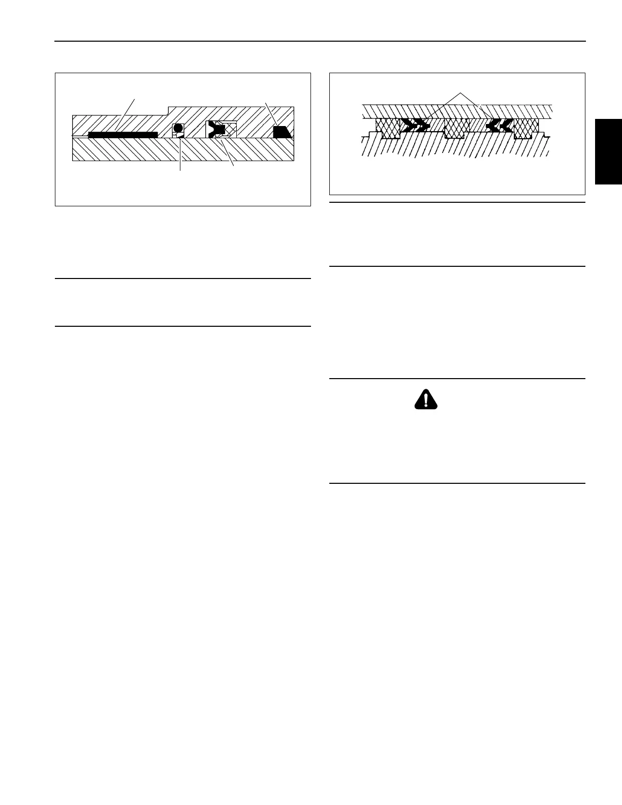
Wiper Ring
Deep Z Rod Seal
Buffer Seal
Wear Ring
FIGURE 2-48
CAUTION
Possible Equipment Damage!
Do not scratch the grooved and gland surfaces or
damage the seals and O-rings.
CAUTION
Flying Parts Hazard!
Use only a source of controlled hydraulic oil pressure to
cycle or pressurize the cylinder.
Parts can fly from the cylinder at dangerous speeds when
using air pressure.
Hydrolock Piston Seals
FIGURE 2-49

 Loading...


