National Crane 01-22-2019 Control # 051-08 4-7
1300A BOOM MAINTENANCE
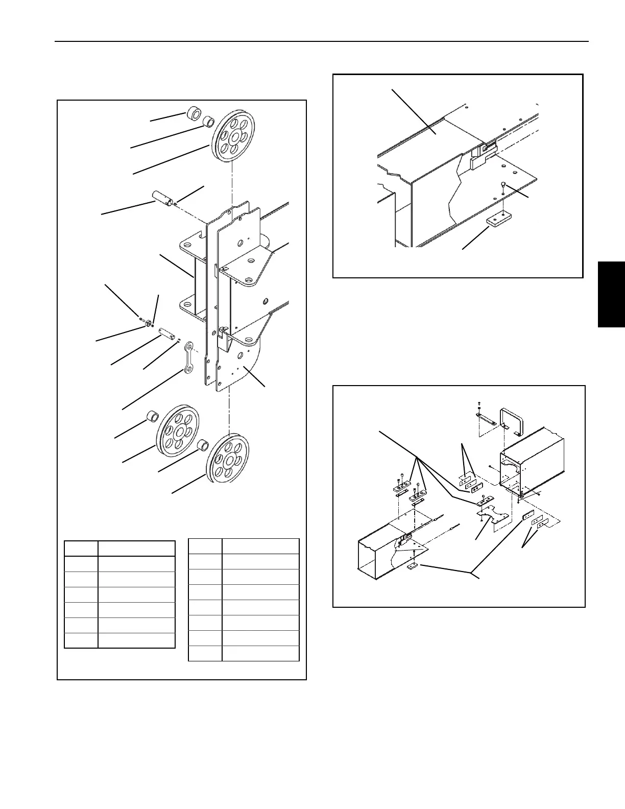
the boom with the spacer to the right hand side
(Figure 4-7).
2. Attach the rear wear pads on bottom of the 4
th
section as
per removal tags. Use Loctite 243 blue on all wear pad
mounting capscrews (Figure 4-8).
3. Install the 4
th
section boom into the 3
rd
section. Slide in
until about 5 feet (150 cm) of the 4
th
section extends
from the 3
rd
section.
4. Assemble the bottom front wear pads for the 3
rd
section
as per removal tags and attach to the pad plate
(Figure 4-9).
5. Using an appropriate lifting device, lift the 4
th
section to
allow for wear pad/pad plate installation in front of the
3
rd
section.
6. Install the wear pad/pad plate assembly and slide the
sections together within 12 inches (30 cm) of full
retraction.
7. Install the cable guide and upper spacer to the front of
the 3
rd
section.
FIGURE 4-7
1
2
3
4
5
6
7
8
9
11
12
13
12
13
10
Item Component
1Spacer
2 Bearing
3 Sheave
4Pin
5 St. Zerk
6 Cap Screw
7Collar
8 Lock Nut
9Pin
10 Zerks (2)
11 Link
12 Bearing
13 Sheave
Item Component
Left Side
Right Side
FIGURE 4-8
Rear of 4
th
Section
Cap Screws
Wear Pad
FIGURE 4-9
Wear Pad
Plate
Shim
(as required)
Shim
(as required)
Wear Pads

 Loading...


