32
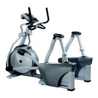
9.5 BEARING PULLEY ASSEMBLY REMOVAL AND INSTALLATION
Figure A
Figure B
Figure C
1. Turn o power and disconnect the cord from the machine.
2. Remove both front disks from machine as outlined in section 9.1
(Figure A).
3. Loosen belt tension bolts as outlined in section 9.4. If removing the
lower assembly, remove the drive belt tensioner. (Figure B)
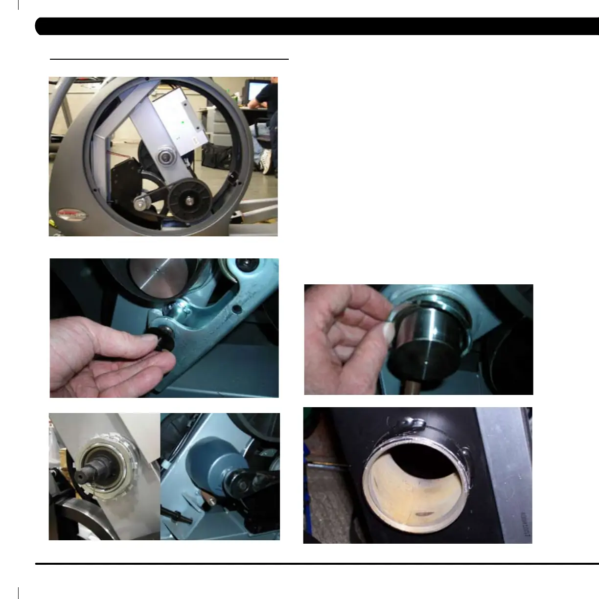
4. Release any bent tabs from locking washer around nut. Remove the
75mm nut from the assembly being serviced. Matrix tness service tool
required. (Figure C)
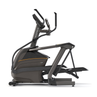
5. Remove the tapered split ring that is held in place by the nut. (Figure D)
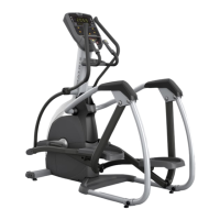
6. Remove the bearing assembly, and clean any debris from the frame.
(Figure E)
7. Reverse steps 1-6 to install new assembly, making sure to tighten
75mm nut to 100 N-m torque and rebend lockwasher tab to secure
nut. (See section 9.4 to install belts.) Test machine as outlined
in 9.99.
Figure D
Figure E