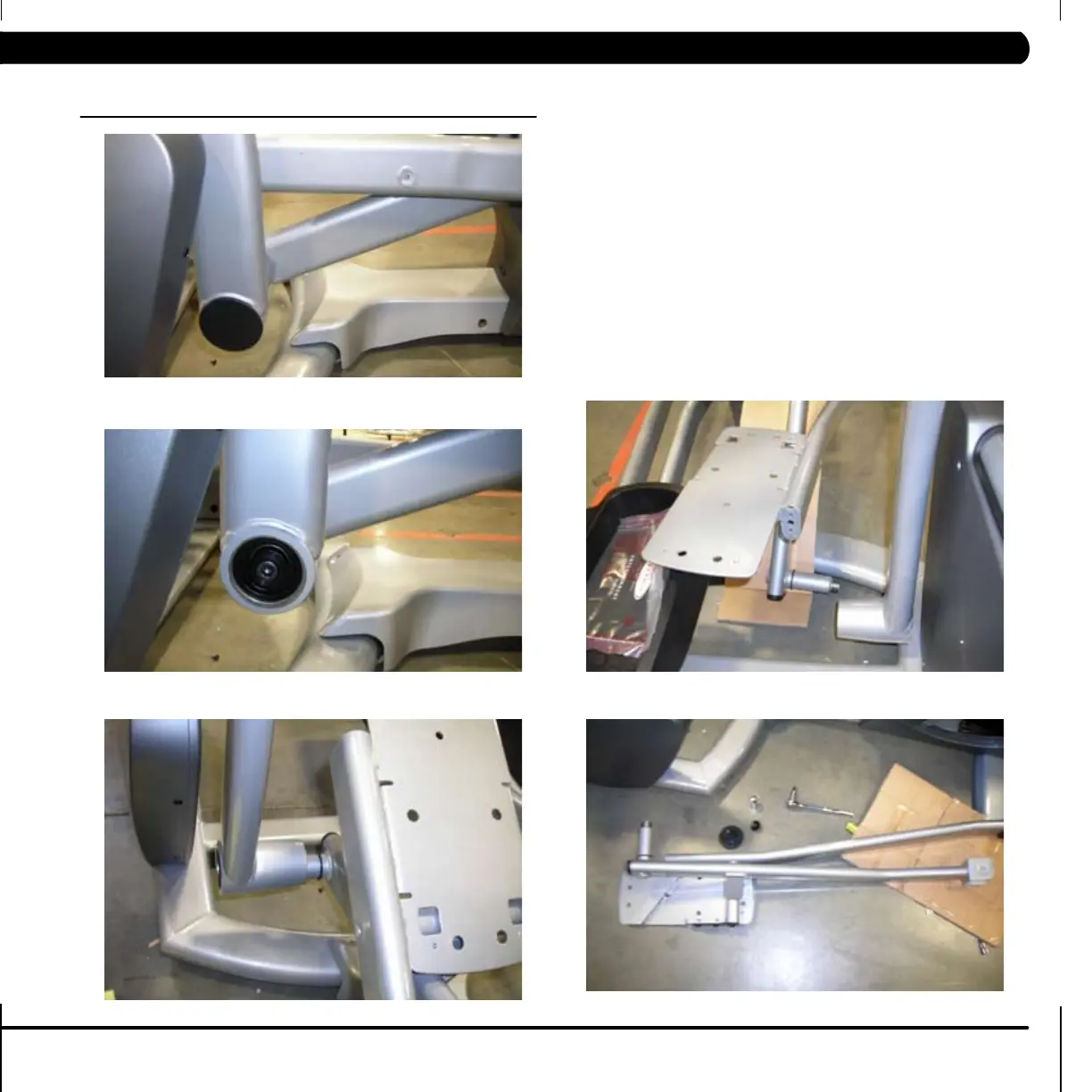
43
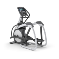
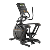
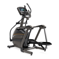
9.12 LINK ARMS & PEDAL ARMS REMOVAL AND INSTALLATION
1. To service or replace link arms and pedal arms they should be
removed from the machine as an assembly. The pedal arm is noted
so as it connects to the front disc assembly. The link arm contains
the foot pedal and connects to the dual action arm in the front.
2. Disconnect the arms from the front of the machine as outlined in
Section 9.1.
3. Disconnect the arms from the rear of the machine by separating the
joint between the swing arm and the pedal arm. Remove the plastic
cap from the swing arm bushing to reveal the bolt and washer that
hold the joint together. Remove the bolt (tighten to 28 N-m torque
during reassembly) and separate the link arm from the swing arm.
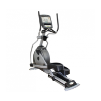
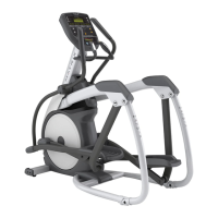
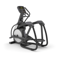
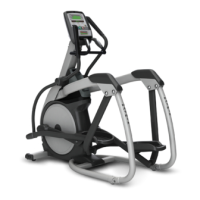
(Figures A, B, C, D, and E)v
Figure A
Figure DFigure B
Figure C
Figure E
CHAPTER 9: PART REPLACEMENT GUIDE