User Manual for the Meca500 Industrial Robot (for rmware 10.1) 7
SAFETY
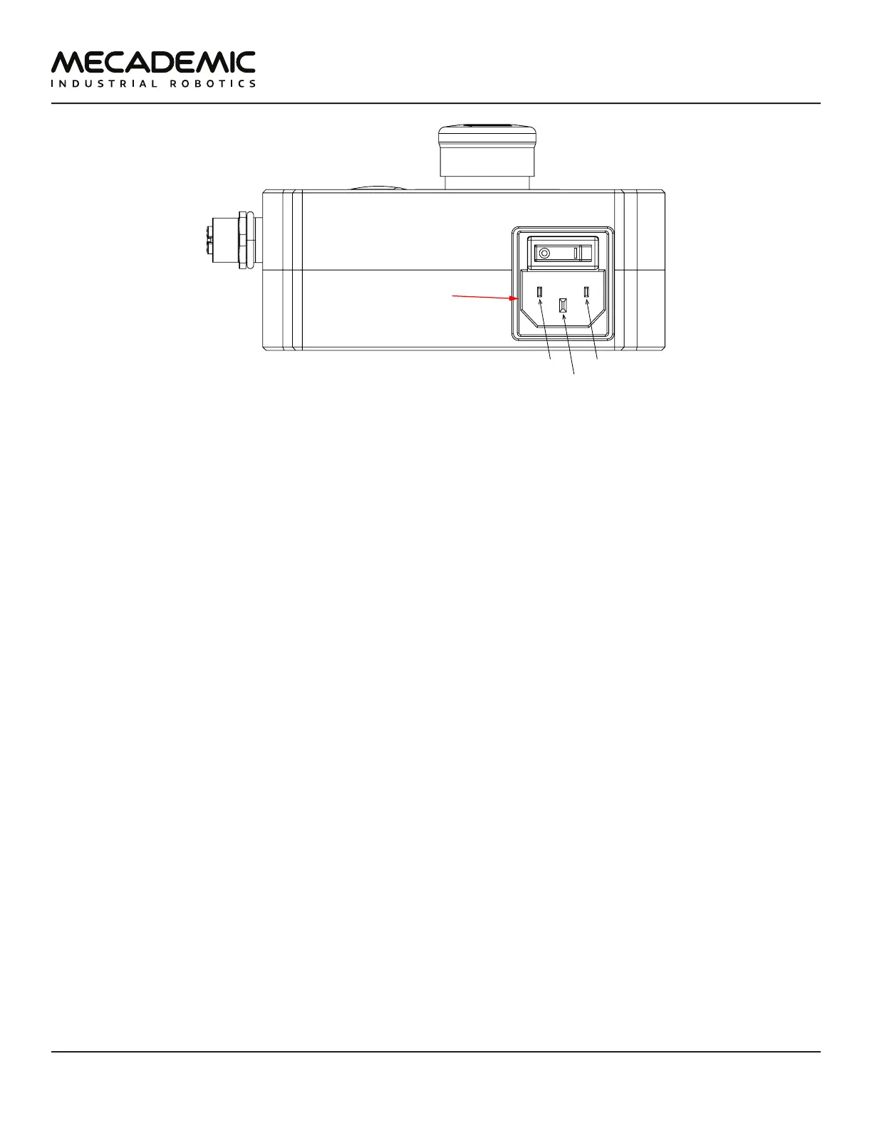
IEC C14
L
N
Figure5: Power supply AC power connector and main switch
The E-Stop circuit of the Meca500 (E-STOP button on PSU and optional external E-Stop buttons that are
properly connected) meets the performance level required by ISO 10218-1:2011 (5.4.2) which is PL=d
with a circuit structure of Category3 based on ISO 13849-1:2006. As per ISO 10218-1:2011 (5.4.2), a
Category 3 structure means that:
– A single fault in any subcomponent does not lead to the loss of the safety functions.
– The single fault shall be detected at or before the next demand upon the safety function.
– When the single fault occurs, the safety function is always performed and a safe state shall be
maintained until the detected fault is corrected.
Safety equipment connected to the Protective Stop 1 function on the D-Sub connector safety input also
meet the same requirements and are PL=d and Category 3.
The E-Stop and Protective Stop 1 circuits on the Meca500 are Stop Category 1, as per ISO 13850:2008
(4.1.4). Once the stop is initiated, the robot arm will stop any motion in a controlled manner in less
than 150 ms. The power is removed from the robot (R3) or from the robot's motors (R4) after 450 ms
regardless of the state of the system.
The E-Stop and Protective Stop 1 inputs are redundant with two separate channels and monitoring
circuitry is used to ensure that no tampering is possible. This means the inputs must switch states in
tandem within 50 ms otherwise a Stop Category 0 will occur (power is removed from the motors).
In order to be able to use the Meca500, you must properly connect your safety inputs on the D-Sub
15-position interface, as described in Section 7 or temporarily connect the D-Sub dongle.
2.2.1 Locking up the power supply
To prevent unauthorized or accidental powering of the robot, we suggest unplugging the AC cord and
using a detachable IEC Plug Lockout device such as the one from Brady.