16 User Manual for the Meca500 Industrial Robot (for rmware 10.1)
INSTALLING THE ROBOT SYSTEM
4. INSTALLING THE ROBOT SYSTEM
Before operating your Meca500, you must fix solidly its base with four M6 screws, at 3 Nm, with at least
6mm of thread engagement. We typically use metric breadboards such as those from Thorlabs, but you
can also use our adaptor plate (MUAP01), build your entire robot cell at Vention, or use the modular
system made by Tessella Automation. We recommend that you use three kinematic positioners to
constraint your base, so that you can always remove and then install it in the exact same location. Our
adaptor plate, for example, incorporates three locating pins.
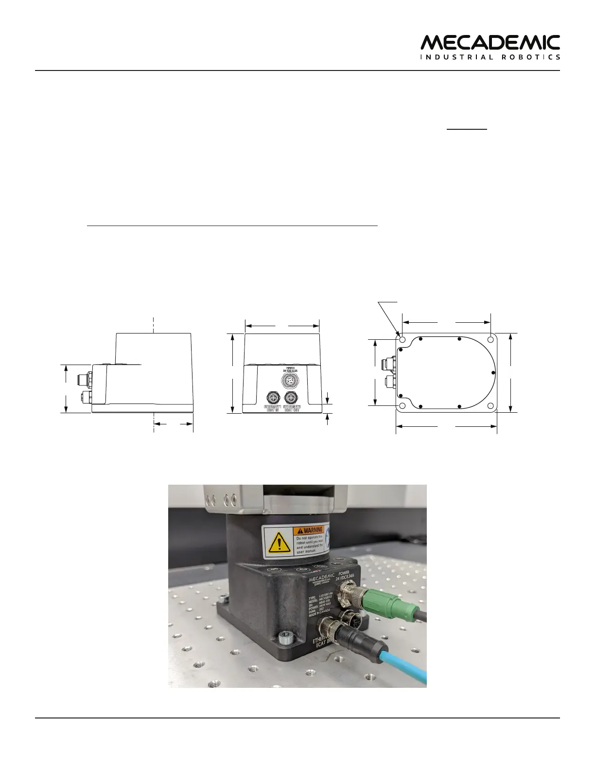
The dimensions of the robot base are shown in Figure10 and an example of installation is shown in
Figure11. Note that you can install the robot base in any orientation. The robot will automatically detect
the angle between the axis of joint 1 and the gravity vector (no need to manually specify this angle). Also,
note that you can mount the robot's base on a mobile body (e.g., on the carriage of a linear guide), but
only if you do not intend to move the robot's joints, while the robot's base is accelerating with respect to
the ground.
115
4X through holes for M6
100
75
90
10
90
a
joint 1
45
84
Figure10: Dimensions of the robot base
Figure11: The robot base installed, with the connectors attached