22 User Manual for the Meca500 Industrial Robot (for rmware 10.1)
OPERATING THE ROBOT
of its joints to their 0° positions. In this robot joint set (shown in Figure9), the robot is in a so-called wrist
singularity. Most industrial robots cannot move in Cartesian mode from such a singularity. In order to
simplify the use of the Meca500, as of firmware 9, we have implemented an algorithm that allows the
robot to move through such a singularity.
The Cartesian coordinates displayed above the robot in the web interface are those of the
Tool Reference Frame (TRF) with respect to the World Reference Frame (WRF). Both frames are
displayed in the web interface. By default, the TRF is located at the flange of the robot and the
WRF at the bottom of the robot's base (as in Figure23). The origin of the TRF is called the TCP
(Tool Center Point).
We use Euler angles (α, β, γ) to define the orientation of a second reference frame with respect
to a first one. More specifically, if we consider both frames initially coincident, we rotate the
second frame about its x axis at α degrees, then about its y axis at β degrees, and finally about
its z axis at γ degrees. This Euler-angle convention is sometimes referred to as XY'Z''.
Thus, for example, you can simply go to the Cartesian tab of the jogging menu, and with the TRF option
selected, press the right arrow button of the x jogging bar. Alternatively, you can perform the same kind
of linear motion by following any of these steps:
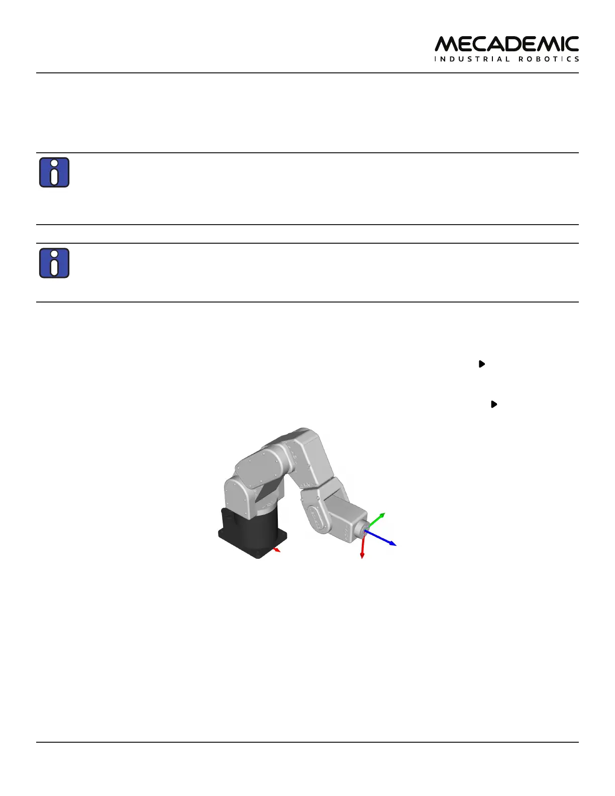
• Clear the programming text field, type MoveLin(250,0,150,0,90,0), and press .
OR
• Clear the programming text field, type MoveLinRelTRF(58,0,0,0,0,0), and press .
Figure18: Robot position when the TRF is at x = 250 mm, y = 0 mm, z = 150 mm, α = 0°, β = 90°, γ = 0° with respect to
the WRF
Figure18 shows the resulting robot position.
5.2.7 Testing the E-STOP button and the brakes (first time use)
Execute a movement command and, while the robot is still moving, press the E-STOP button on the
smart power supply. The power supply completely cuts power to the robot, in the case of R3 version,
or only to the robot motors and Mecademic's EOAT, in the case of R4 version. In both cases, the robot
brakes will be automatically applied to joints 1, 2 and 3. If joints 1, 2 or 3 continue to move, or if you
notice that the even after powering off the robot, one or more of these joints can be as easily rotated by
hand as joints 4, 5 and 6, cease using the robot immediately and contact us immediately.