44 User Manual for the Meca500 Industrial Robot (for rmware 10.1)
OPERATING THE SMART POWER SUPPLY
Never connect or remove the D-Sub dongle or add or remove safety I/O connections, while the
power supply is on.
As already mentioned, you can connect:
• one Stop Category 1 emergency stop (pins E-Stop – A1, E-Stop – B1, E-Stop – A2, E-Stop – B2);
• one Stop Category 1 protective stop (pins P-Stop 1 – A1, P-Stop 1 – K1, P-Stop 1 – A2, P-Stop1 – K2);
• one software stop (pins SWStop – A, SWStop – B);
• one reset (pins Reset – A, Reset – K);
• one power status indicator (pins Power Status – A, Power Status – B).
7.3.1 Stop Category 1 Emergency Stop
The external E-Stop performs the same function as the E-Stop on the power supply. The terminals
of the external E-Stop are connected in series with the E-Stop on the power supply. Figure27 shows
two examples for the wiring of the four external E-Stop terminals. You may also, for example, connect
several E-Stops in series or use a safety PLC. If you choose not to use any external E-Stop, remember to
wire the pins as in Figure27b.
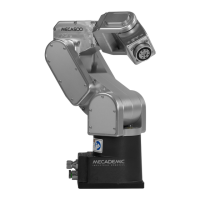
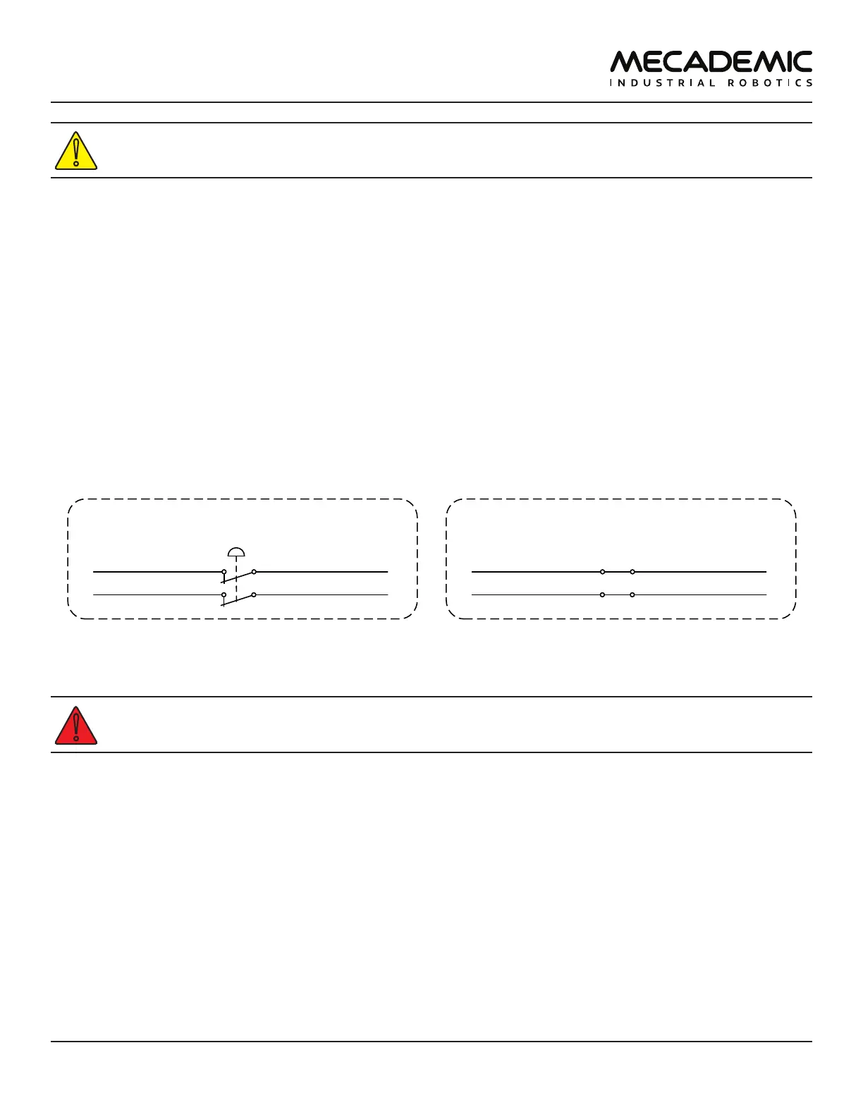
External E-Stop
E-Stop – A1 (1) E-Stop – B1 (9)
E-Stop – A2 (2) E-Stop – B2 (10)
External E-Stop, when not used
E-Stop – A1 (1) E-Stop – B1 (9)
E-Stop – A2 (2) E-Stop – B2 (10)
(a) Wiring when an external E-Stop is used (b) Wiring when no External E-Stop is used
Figure27: Examples of wiring of the external E-Stop connections
The external E-Stop circuit must be closed for the robot to be able to move.
7.3.2 Stop Category 1 Protective Stop (P-Stop 1)
Figure28 shows the wiring diagram for the P-Stop 1 terminals in the case of the R3 and R4 versions of
the Meca500. The P-Stop 1 signal would generally come from a safety PLC, which will be connected to a
safety switch such as a safety light curtain or an interlock door switch.
Note, however, that in the R3 version, the current that reaches the power supply at the P-Stop 1
terminals must be a 24mA continuous forward current. This is why the use of proper resistances is
compulsory in the R3 (see Figure28a), or else you will damage the power supply.
In the case of the Meca500 R4, a current limiting circuitry has been implemented, and the use of a
resistance is not necessary.