Do you have a question about the Mecademic Meca500 and is the answer not in the manual?
Lists items included with the Meca500 robot system.
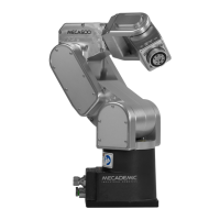
Describes the Meca500 robot arm, its joints, and brake system.
Lists European directives and harmonized standards for Meca500 R4.
Explains the robot operates only in automatic mode within a safety enclosure.
Details the PS-200 power supply's safety features and usage guidelines.
Discusses robot arm components and associated safety considerations.
Explains brakes on joints 1-3 and absence on 4-6, noting potential residual motion.
Describes procedures for releasing brakes for manual robot movement.
Provides data on robot stopping times and distances under various scenarios.
Mentions mechanical and software limits for robot joint ranges.
Discusses setting and limitations of joint torque limits.
Explains robot behavior upon losing Ethernet connection.
Covers initial setup steps for the robot.
Connects D-Sub dongle for initial setup and maintenance.
Sets up computer's static IP for robot connection.
Steps to power on the robot and its supply.
Steps to power on the robot and its supply.
Accessing the robot via its web interface (MecaPortal).
Modifying network settings (IP, DHCP) via MecaPortal.
Process to activate and home the robot.
Procedure to test joint 6 orientation.
General guidance on robot movement and limitations.
Verifies E-STOP button and brake functionality.
Steps to safely power off the robot.
Steps to move joints to zero position before powering off.
Procedures to deactivate the robot.
How to disconnect the web interface from the robot.
Steps to remove power from the supply.
Overview of buttons and LEDs on the robot's base.
Explains functions of buttons on the robot's base.
Describes the meaning of LEDs on the robot's base.
How to use offline mode for demonstrations.
How to save a program using the web interface.
How to execute an offline program from the control panel.
Guide to updating robot firmware via the web interface.
Overview of the MecaPortal web interface elements.
Details the components of the MecaPortal menu bar.
Explains connection status and robot state indicators.
Introduces the panel for writing and testing robot programs.
How to create, save, and manage programs in the editor.
Details syntax highlighting, auto-completion, and context menus.
How to execute programs and manage motion commands.
Describes the panel that lists commands and responses.
Explains the panel showing robot position and 3D model.
Information on how robot position is displayed.
Panel for controlling robot movement.
How to jog robot joints using various input methods.
How to jog robot in Cartesian space using various inputs.
Accessing robot settings and options via the configuration menu.
Details the different types of stops available on the power supply.
Explains the status and error LEDs on the power supply.
Describes safety circuit connections to the D-Sub connector.
Wiring for external E-Stop connections.
Wiring for P-Stop 1 terminals.
Wiring for SWStop signal from safety PLC.
Wiring for external reset signal.
Wiring for power status output terminals.
Example program for drawing a square path.
| Degrees of Freedom | 6 |
|---|---|
| Payload Capacity | 0.5 kg |
| Control Interface | Ethernet |
| Power Supply | 24 V DC |
| Controller | Integrated |
| Protection Class | IP40 |
| Type | Industrial robotic arm |
| Repeatability | 5 μm |