User Manual for the Meca500 Industrial Robot (for rmware 10.1) 49
INSTALLING AN END-EFFECTOR
8. INSTALLING AN END-EFFECTOR
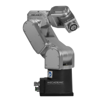
The Meca500 comes with a proprietary tool I/O (input/output) port located at the robot extremity
(Figure32a). However, this tool port is reserved uniquely for our end-of-arm-tooling (EOAT), i.e., our
electric grippers MEGP 25E and MEGP25LS, and our pneumatic module MPM500. We do not share the
pinout of this port or its custom-made communication protocol. To install our grippers or pneumatic
module, refer to their user manuals.
If you want to use any other end-effector with the Meca500, you will need to control it independently
from the Meca500. You can attach the cabling of your end-effector along the robot arm using adhesive-
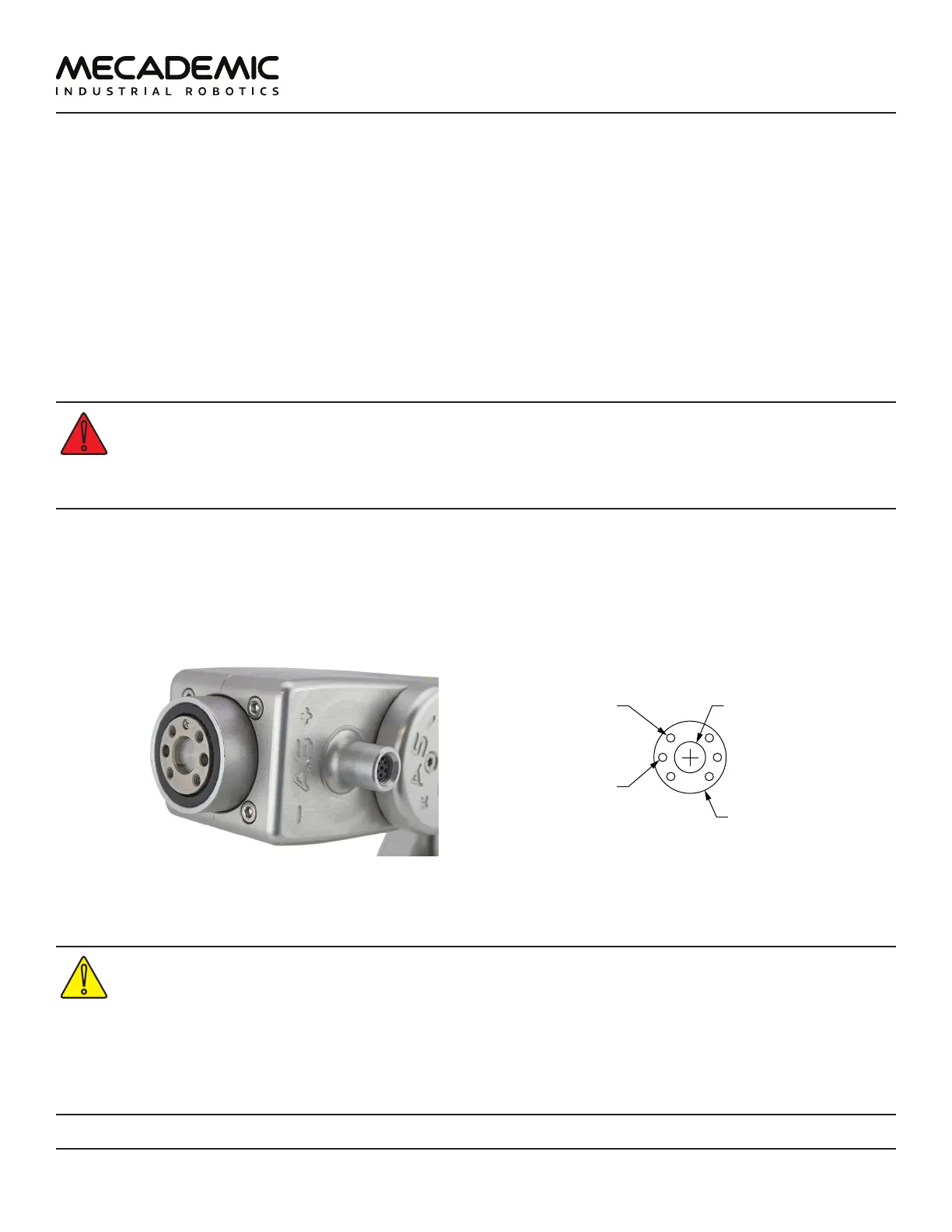
backed tie mounts. Finally, you must fix the end-effector to the robot's flange (Figure32b) using four M3
screws tightened at 1.5 Nm, and, optionally, one ⌀3 locating pin, all of properly selected length.
• Keep the robot unpowered while installing/removing a tool to its flange.
• Do not exceed the robot payload (0.5 kg).
• Do not exceed 3.4 Nm for the moment load on the robot flange.
• Securely fasten the tool to the robot flange.
Note that since joint 6 is multi-turn, there is no way of knowing the angle of joint 6 (even approximately),
unless the robot is activated and homed. Therefore, prior to mounting an end-effector, it is important
that you activate and home your robot, rotate joint 6 to its zero position, and finally unpower the robot.
However, if the screw on the flange of the robot is not as in Figure32a when θ
6
= 0°, then you need to
follow the procedure described in Section Homing of the Programming Manual.
Ø20
units: mm
Ø9 H6, É2.2
M3X0.5,
É4
BCD 15.5
4X equally spaced
Ø3, É3.5
BCD 15.5
2X equally spaced
(a) closeup (b) dimensions
Figure32: The mechanical interface (ange) of the Meca500. The ange is the ⌀20 disk, inside the black isolation
ring, and is the only one to rotate when joint 6 rotates.
• Make sure that joint 6 is approximately at 0° before attaching an end-effector.
• Tighten the M3 screws with a torque of 1.5 Nm and a thread penetration of 4 mm. Do not
thread more than 4 mm into the flange or else you may damage the gearbox of joint 6.
• Attach the tool cabling in such a manner that it obstructs as little as possible the motions
of the robot.
• Unless you plug the connector of one of our own EOAT, keep the cover (screw cap, not
shown in Figure32a) of the tool I/O port in place at all times.