User Manual for the Meca500 Industrial Robot (for rmware 10.1) 45
OPERATING THE SMART POWER SUPPLY
V
in
External protective stop 1
(Stop Category 1)
P-Stop 1 – A1 (4)
P-Stop 1 – K1 (12)
P-Stop 1 – A2 (5)
P-Stop 1 – K2 (13)
Inside power supply
R
R
V
in
5 V ≤ V
in
≤ 24 V
R = V
in
/ 0.024
P
res ≥
V
in
²
/ R
V
in
External protective stop 1
(Stop Category 1)
P-Stop 1 – A1 (4)
P-Stop 1 – K1 (12)
P-Stop 1 – A2 (5)
P-Stop 1 – K2 (13)
Inside power supply
V
in
5 V ≤ V
in
≤ 24 V
current
limiter
current
limiter
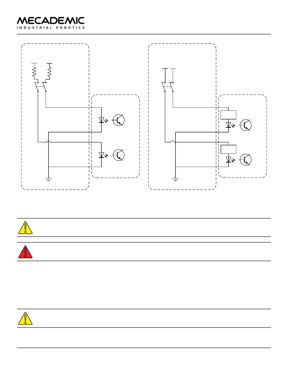
(a) Wiring the P-Stop 1 in the Meca500 R3 (b) Wiring the P-Stop 1 in the Meca500 R4
Figure28: Examples of wiring the P-Stop 1 in the Meca500 R3 and R4
In the Meca500 R3, you MUST USE RESISTANCES to limit to current applied to the P-Stop 1
terminals to 24mA, or else you will damage the power supply.
The P-Stop 1 circuit must be closed for the robot to be able to move.
7.3.3 Software Stop (SWStop)
The software stop is essentially equivalent to sending the command PauseMotion.
The SWStop signal would normally come from a safety PLC. Simple examples for the wiring diagrams in
the case of the R3 and R4 versions of the Meca500 are shown in Figure29. The same specifications for
the input voltage and current apply, as in the case of the P-Stop 1, as shown in Figure29.
In the Meca500 R3, YOU MUST USE RESISTANCES to limit to current applied to the SWStop
terminals to 24mA, or else you will damage the power supply.