User Manual for the Meca500 Industrial Robot (for rmware 10.1) 43
OPERATING THE SMART POWER SUPPLY
Table 12 summarizes the different states of the three LEDs as well as their meanings.
Table 12: The various states of the LEDs on the power supply
POWER SUPPLY LEDS
LED Name LED state Explanation
Green Power
Off
The power supply is turned on
On
The power supply is turned off
Yellow Status
Off
Robot is not powered. Press RESET.
Blinking Robot is not powered and a Stop Category 1 stop is pressed or the dongle is
not plugged in. Remedy the situation and press RESET.
Two flashes Robot is not powered because a RESET button has been pressed for too long.
Press RESET again.
On
Robot is powered.
Red Error
Off
There is no error.
Flashes
No proper robot connected.
Two flashes Robot has detected a problem and requested that power be shut down.
Contact our support team.
Blinking Problem with Stop Category 1 stops detected. Check external stop
connections and contact our support team if no solution found.
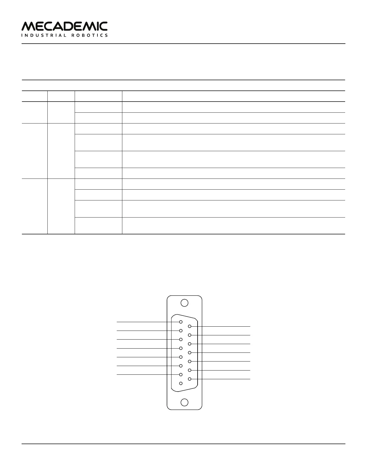
7.3. External connections
The D-Sub dongle is a temporary bypass device. After performing a risk assessment for your installation,
you must design and connect the appropriate safety circuit to the D-Sub connector. Figure30 shows the
pinout of that connectors.
1
8
15
9
E-Stop – A2
P-Stop 1 – A2
SWStop – A
Reset – A
E-Stop – A1
E-Stop – B1
Power Status – A
E-Stop – B2
Power Status – B
P-Stop 1 – A1
P-Stop 1 – K1
P-Stop 1 – K2
SWStop – K
Reset – K
Figure26: Pinout of the D-Sub connector on Meca500's power supply