8 User Manual for the Meca500 Industrial Robot (for rmware 10.1)
SAFETY
2.3. Robot arm and safety
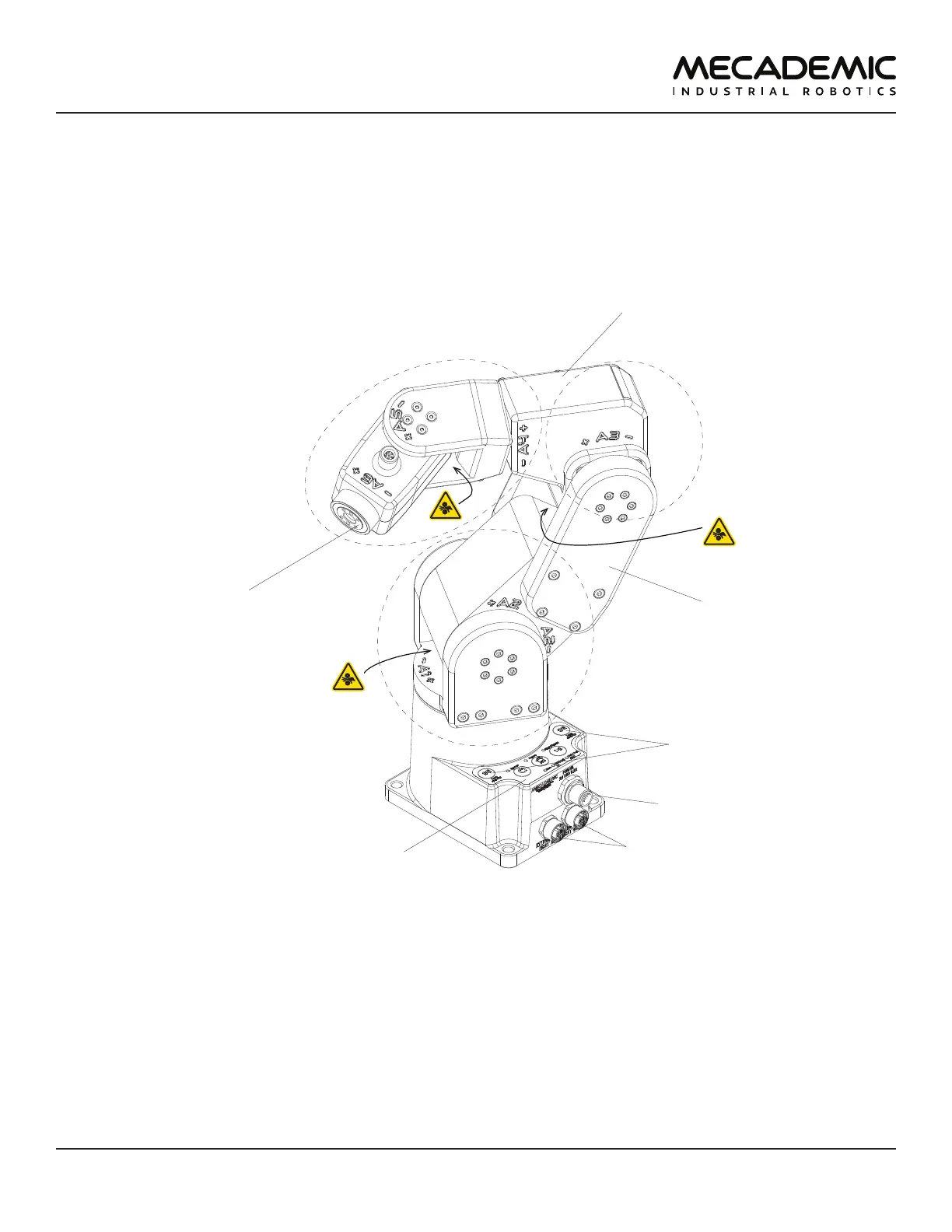
Figure6 shows a description of the main components of the Meca500 robot arm.
DC power connector
flange
(mechanical interface)
0G buttons
control panel
M12 Ethernet connectors
wrist
upper arm
shoulder
elbow
Figure6: Meca500 robot arm
2.3.1 Brakes and limitations
As already mentioned, the Meca500 has brakes on joints 1, 2 and 3 only. Therefore, when the robot is
deactivated, powered off, or put in safety stop (E-Stop or Protective Stop 1), the brakes on joints 1, 2 and
3 will be immediately applied and the joints will be immobilized instantly. Simultaneously, since joints 4,
5 and 6 do not have brakes, they will become free. This minimizes the risks of pinning and pinching from
the wrist and the end-effector. However, beware that the end-effector might slowly move downwards
under the effects of gravity, as shown in Figure7. Depending on the type of end-effector used, this
residual motion might lead to an injury.