24 User Manual for the Meca500 Industrial Robot (for rmware 10.1)
OPERATING THE ROBOT
5.4. Robot control panel
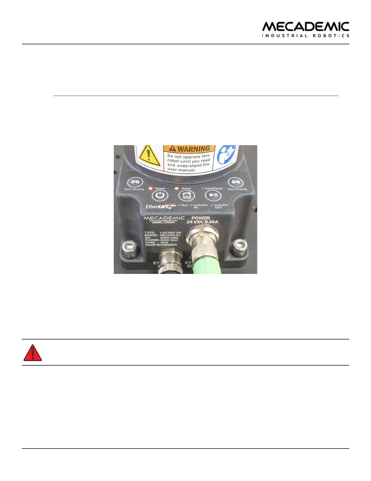
The set of buttons and LEDs on the robot's base is called the robot's control panel (Figure19). The
meanings of the LEDs and the functionalities of the buttons will be summarized in what follows.
Note that these buttons and LEDs are intended mainly for development and demonstration purposes,
as they will not be physically accessible and possibly not visible during a normal operation of the robot,
where the robot is fenced. The information conveyed from these LEDs and the actions controlled by
these buttons are all available in the MecaPortal. The only exceptions are the Link/Act LEDs and the Run
LED. The information conveyed by the Run LED, used only when the robot is controlled via EtherCAT, is
accessible by the EtherCAT master.
Figure19: Robot control panel
5.4.1 Buttons
When the robot is powered and deactivated, the 0G button is active but the other buttons are active
only when no user is connected to the robot. In what follows, you must refer to the detailed descriptions
of the commands associated with each button.
When pressing the buttons on the robot's base, keep your fingers away from the pinch points of
the robot, and move away from the robot as soon as a button is released. These buttons are for
development purposes only. They do not meet the requirements of ISO 10218-1:2011.
Power button
The Power button acts as the ActivateRobot and DeactivateRobot commands:
• when the robot is deactivated, pressing Power will send the ActivateRobot command.
• when the robot is activated, pressing Power will send the DeactivateRobot command.
• when the robot is in error mode, pressing and holding Power for five seconds will send the
DeactivateRobot command.
Pressing and holding Power during power-up will reset the robot network configuration.