2 User Manual for the Meca500 Industrial Robot (for rmware 10.1)
INTRODUCTION
1.2. Overall description
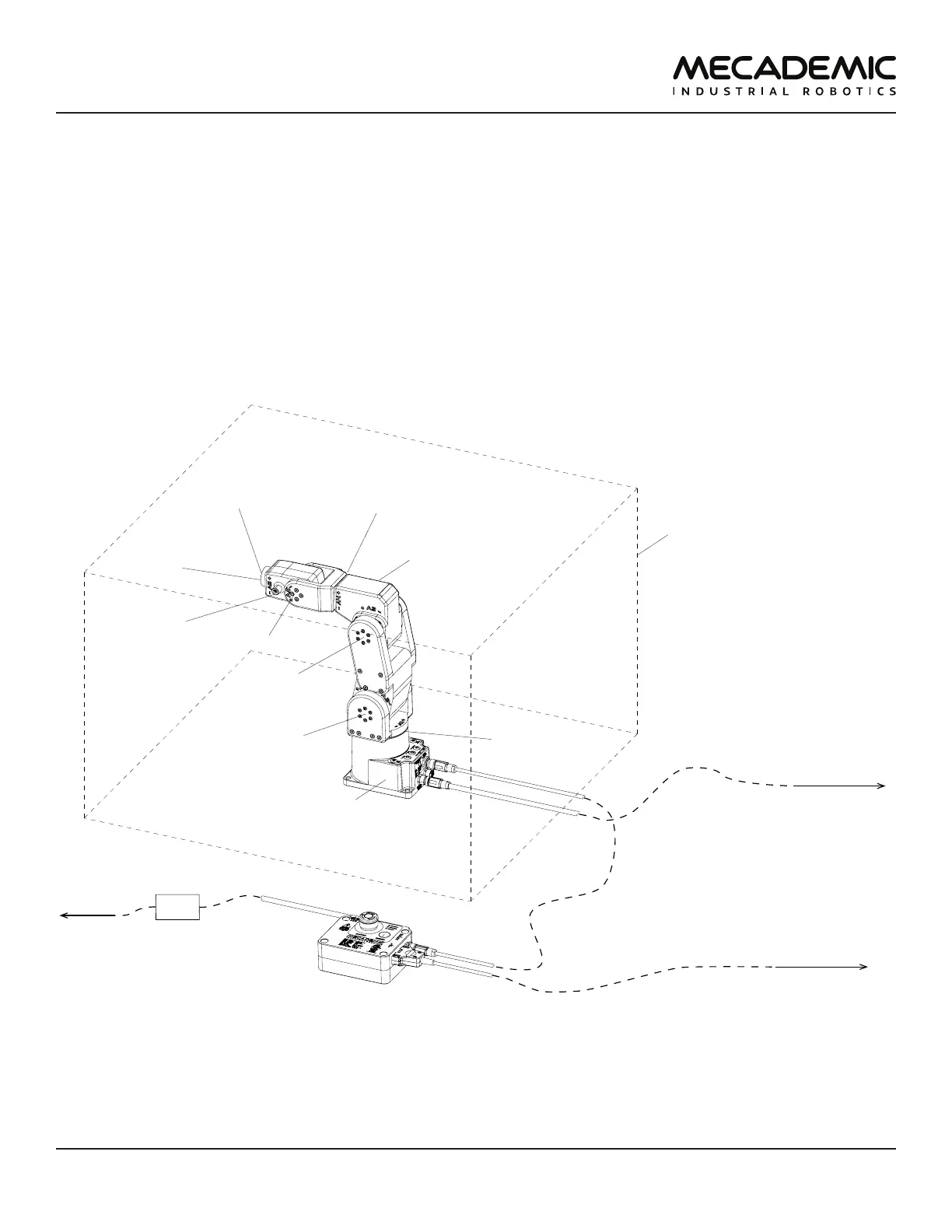
Figure1 shows a schematics of the complete Meca500 robot system in a typical installation. The D-Sub
15-pin dongle provided is not shown as it must be used only during setup and testing. We suggest using
the ASCO Model 241 from Schneider Electric
The Meca500 robot arm consists of seven bodies connected in series through six motorized revolute
joints. The first body is the robot base and the seventh body is the flange (mechanical interface). The
joints are numbered from 1 to 6 , starting from the joint connected to the base, and are labeled on the
robot as A1, A2, ..., A6.
Joints 1, 2 and 3 are equipped with emergency brakes, which are automatically applied when power is
removed from the motors. Joints 4, 5 and 6 have no brakes.
safeguarded enclosure
(not supplied)
power supply
robot arm
surge protector
(not supplied)
DC power cable (2m)
Ethernet cable
with RJ45 jack (2m)
AC power cord
(not supplied)
to computer
or PLC
to standard
electrical
outlet
to safety I/Os
DB15 D-Sub cable
(not supplied)
flange
(for attaching
EOAT)
I/O port for
optional
Mecademic
EOAT
joint 1
(with brake)
joint 2
(with brake)
joint 3
(with brake)
joint 4
joint 5
joint 6
Figure1: Schematics of the Meca500 robot system installed