User Manual for the Meca500 Industrial Robot (for rmware 10.1) 13
TECHNICAL SPECIFICATIONS
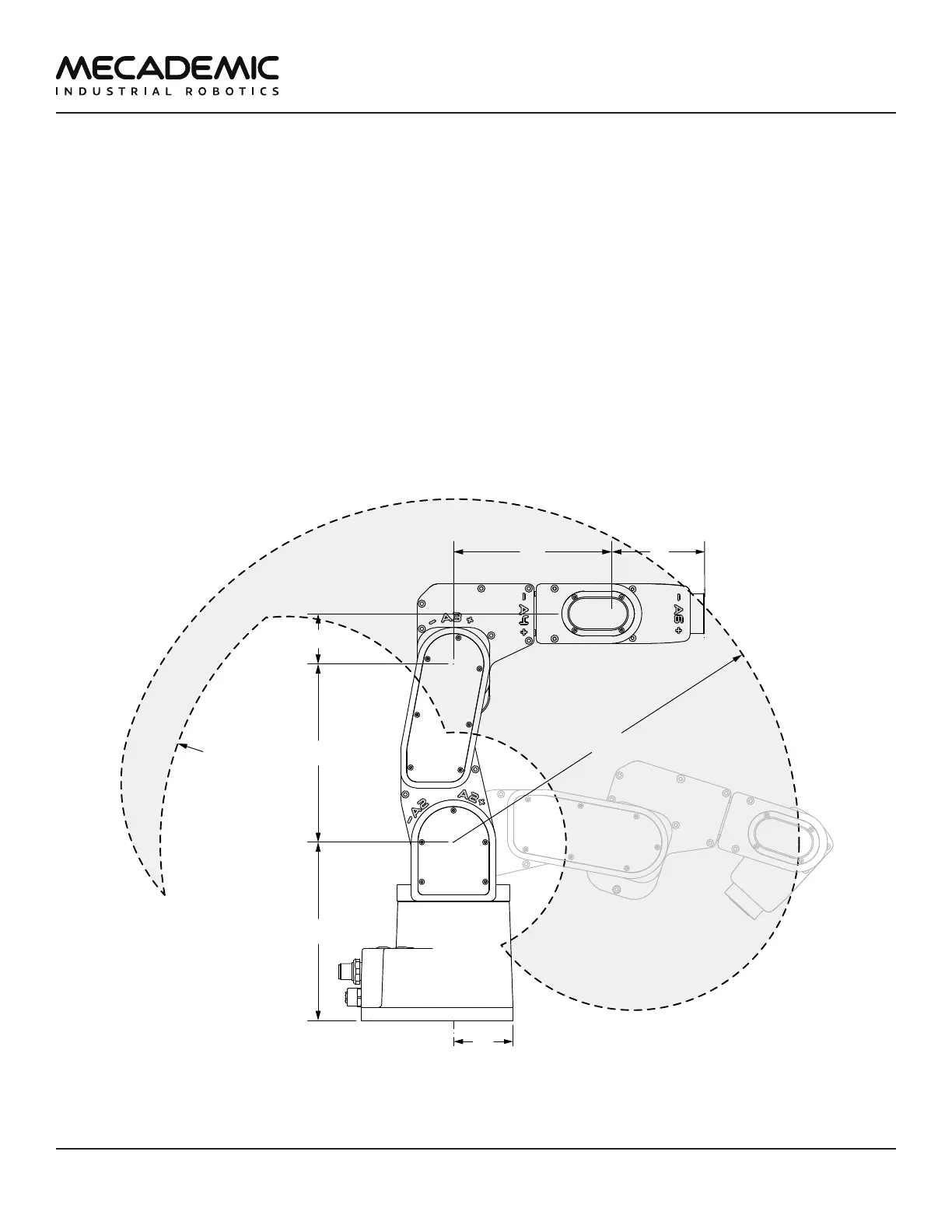
Figure9 shows all the link lengths and offsets of the Meca500, necessary for obtaining the so-called
Denavit-Hartenberg parameters. Note that all joints are at zero degrees in the configuration drawn
in black line. Also note that the gray zone is the area attainable by the center of the robot's wrist
center (the intersection point of the last three axes), for a fixed angle of joint 1. This area, or even the
volume obtained by sweeping this area about the axis of joint 1 is NOT the workspace of the robot. The
workspace of the robot is a six-dimensional entity depending on the definition of the tool reference
frame. The workspace is the set of all attainable poses (positions and orientations) of the tool reference
frame with respect to the robot's base. Even for a specific choice of a tool reference frame, it is
impossible to represent this six-dimensional workspace (read this tutorial of ours).
Similarly, while the maximum tool-center point (TCP) speed is software limited to 5,000 mm/s when
the robot executes Cartesian-space motion commands, it makes little sense to specify here the actual
maximum attainable TCP speed. Indeed, the actual maximum TCP speed is highly dependent on the
robot joint position and, of course, on the TCP definition. For example, for a TCP that is located some
50mm away from the robot's flange, along the axis of joint 6, the maximum attainable TCP speed is
approximately 3500mm/s for the Meca500 R4, when the robot is fully stretched and all joints rotate at
full speed. However, in most situations, the maximum TCP speed will be much lower.
135 135
38
120
70
R260
boundary for
wrist center
Figure9: The dimensions of the Meca500 (R3 and R4)
Table 5 lists the technical specifications of the PS200 power supply that comes with the Meca500.