User Manual for the Meca500 Industrial Robot (for rmware 10.1) 17
INSTALLING THE ROBOT SYSTEM
Do not install any end-effector yet. We will cover this topic in Section 8.
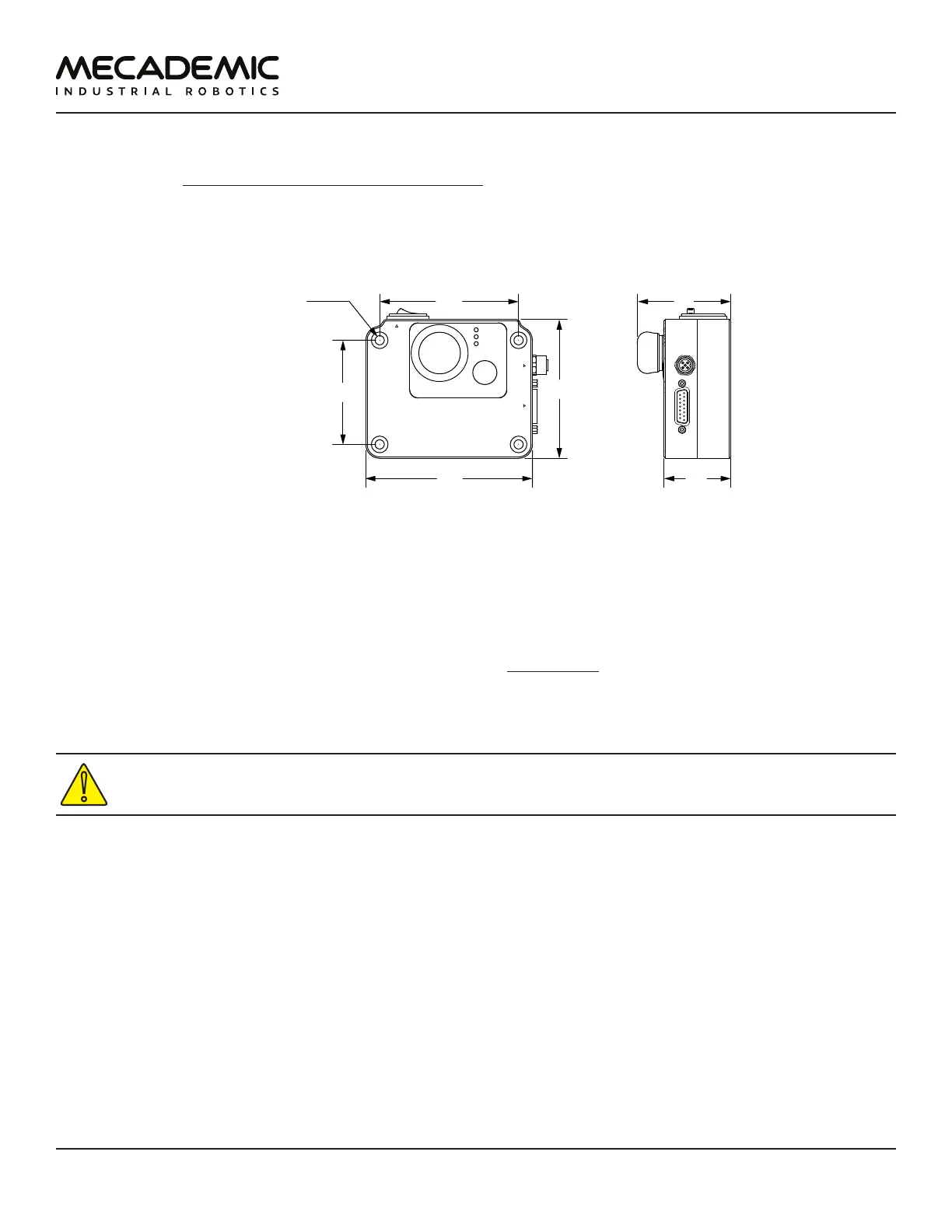
Next, you must solidly attach the smart power supply using four M6 screws (Figure12), at a location
sufficiently close to the robot's base to allow connection with the 2-meter DC cable provided, but outside
the robot's safety enclosure. Unless you are using an external emergency stop wired via the D-Sub
connector, you must fix the power supply at a location that makes the integrated E-STOP button readily
accessible by an operator.
Power
Status
Error
RESETE-STOP
Safety I/O
Port
Robot Power
24 VDC 8.34 A
AC Power
90-264 VAC
50-60 Hz
counterbore
holes for M6
(↧6)
120
90
75
48
Figure12: Dimensions of the PS200 smart power supply
Next, attach the circular connector of the Ethernet cable to the ETHERNET1 port on the robot's base and
connect the RJ-45 jack to your computer or router (Figure11). The two Ethernet ports on the robot base
act as a bridge, so you can daisy-chain several Meca500 robots, or connect an Ethernet I/O module on
the ETHERNET2 port.
Finally, use the DC power cable provided to connect the unpowered power supply to the robot's DC
power connector (Figure11). Make sure the connectors are completely screwed, or else you may
damage the robot. Then, connect the power supply to your country-specific AC power cord (not
provided).
Always connect the DC power cable before connecting the power supply to an AC outlet. Always
disconnect the power supply from the AC outlet before disconnecting the DC power cable.