Have a question or need assistance?
Call Medicomp’s Patient Support: 877-996-5553
electrode patch application). Please follow the skin preparation sequence as closely as possible.
This will greatly enhance the ECG signal quality and optimize analysis.
Electrode Placement for the Tele
Patch Procedure
Step 1 - Identify Electrode Sites
5-Wire Hook-up: Lead II and a modified Lead V1 or MCL1 are used with the Tele
Patch Cable
Cradle procedure, which provides two-channel, ambulatory monitoring. "A" in the table below
corresponds to Lead II. "B" in the table corresponds to V1/MCL1. [Referring to the Medicomp
reports, the ECG strips show Lead II at the top, and Lead V1/MCL1 on the bottom.
3-Wire Hook-up: Lead II and Lead I are used. [Referring to the Medicomp reports, the ECG
strips show Lead II at the top, and Lead I on the bottom
.
Refer to the figures below for proper electrode placement:
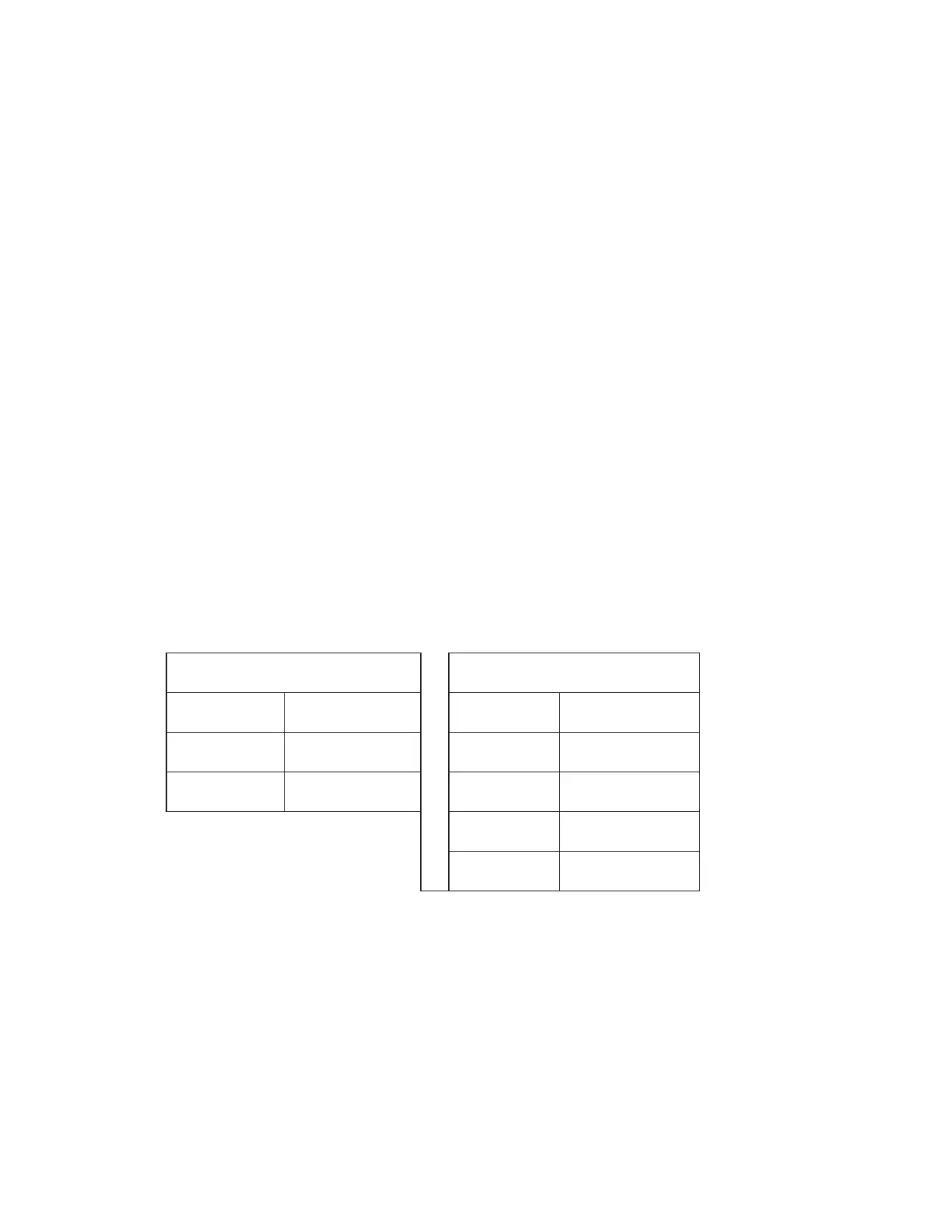
3-Wire Hook-Up
5-Wire Hook-Up
A- WHITE A- WHITE
A+ / B+ RED A+ RED
B- BLACK B- BLACK
B+ BROWN
G GREEN
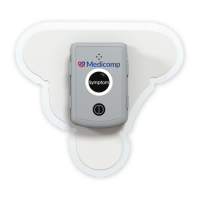
Tele
Patch™ Cardiac Monitor PM750
USER MANUAL - UTM0000701-05E
| APRIL 4, 2019
48