HELIOS LED Processing Platform - USER GUIDE 101
F
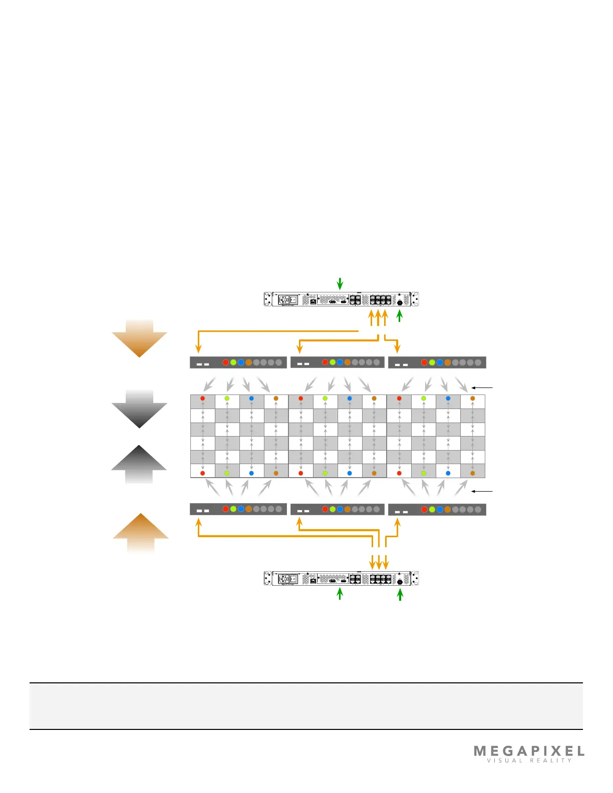
Data Redundancy
Overview
The HELIOS system supports multiple high availability redundancy modes. This is accomplished by sending video data
from two HELIOS Processors to the same string of tiles at once using bidirectional data ow from each end of the tile
string simultaneously. Illustrated below, are two HELIOS processors and associated switches sending data into strings of
tiles from two directions (top down and bottom up). HELIOS Junior units can also be used to create redundant systems. In
the case of HELIOS Junior, the processors send data directly to tiles without the use of network switches. Since there is
duplicate data on the network, tiles need to know which processor to listen to. This is done by a system of priority. The
processor with the role Main has the highest priority. All of the processors must be connected to an external genlock sync.
Figure 134: Redundant system topology
NOTE: Tiles must have software version 20.03.0.256 or later to support the HELIOS redundancy features. See the end
of this section for upgrade steps.
Sync
10G, LC Single Mode Fiber
Up to 10km in length
HELIOS Processor - REDUNDANT
Video Source
HDMI
SDI
Display Port
Cat6 from switch to
first tile in chain.
Network Switch 1
1 2
4 5
6 7
8
3
9 10
Network Switch 3
1 2
4 5
6 7
8
3
9 10
Cat6 from switch
to first tile in
chain.
HELIOS Processor - MAIN
10G, LC Single Mode Fiber
Up to 10km in length
Video Source
HDMI
SDI
Display Port
4 x Cat6 cables
4 x Cat6 cables 4 x Cat6 cables 4 x Cat6 cables
4 x Cat6 cables4 x Cat6 cables4 x Cat6 cables
Network Switch 2
1 2
4 5
6 7
8
3
9 10
Network Switch 4
1 2
4 5
6 7
8
3
9 10
Network Switch 5
1 2
4 5
6 7
8
3
9 10
Network Switch 6
1 2
4 5
6 7
8
3
9 10
CAT6 DATA FLOW
CAT6 DATA FLOW
FIBER DATA FLOW
FIBER DATA FLOW
MAIN DATA
REDUNDANT DATA
Sync
 Loading...