HELIOS LED Processing Platform - USER GUIDE 5
Network Switch Overview
The HELIOS system leverages network switches, like the GSM4210P, for data distribution to the tiles. The network switch
connects to the HELIOS processor via 10Gb ber SFP+ uplink and has eight 1 / 2.5Gb copper Ethernet ports that serve as
outputs to the display. Systems may have up to eight switches per HELIOS and are typically co-located with the display. All
user controllable functions of the network switch are accessed via the HELIOS web UI.
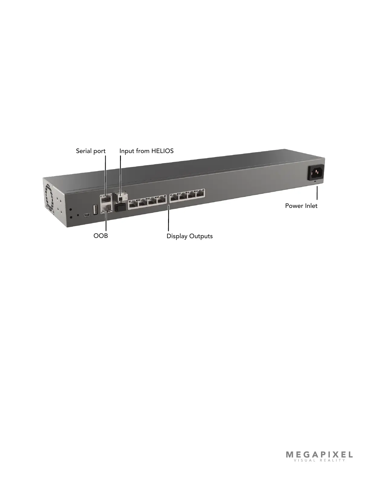
Input - 10Gb ber SFP+ input, receives display data from HELIOS processor.
Display Outputs - 1 / 2.5Gb copper Ethernet ports, transmits video and control data to and from connected panels.
Power - IEC C14 A/C power connector. The network switch will boot as soon as power is supplied.
Figure 5: GSM4210P network switch I/O.
Input from HELIOSSerial port
OOB
Display Outputs
Power Inlet