HELIOS LED Processing Platform - USER GUIDE
8
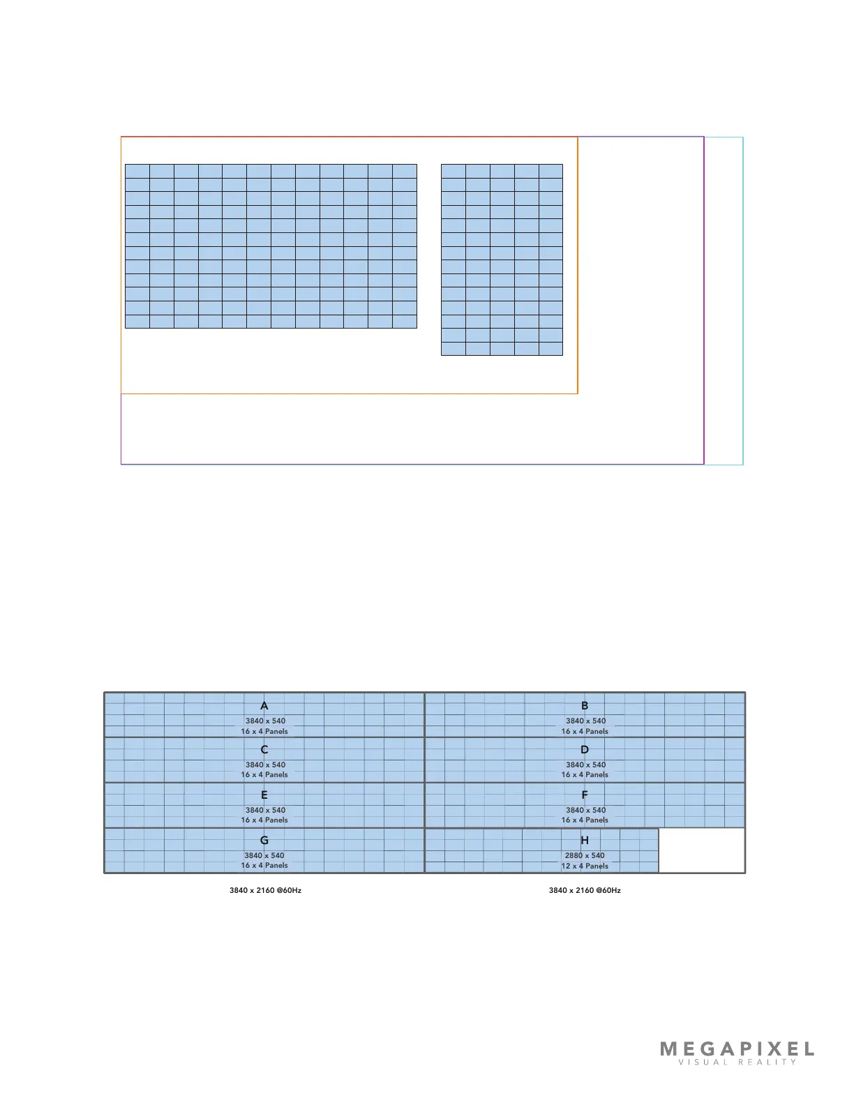
Creating a Raster Map
It is a good idea to create a raster map drawing to document which portion of the video signal serves which portion of the
display. The example below contains two separate displays (blue tiles). In this case, the pixel dimensions of both displays
will t on a 6K raster. The larger 8K and DCI 8K rasters are shown for reference.
Figure 7: Example raster map
Sometimes, the ‘as built’ shape of the system does not t any horizontal or vertical rasters, but the total number of pixels
can. This is the case with a long ribbon display. Rasters can be rearranged, (within certain limitations) on the front end if
necessary. In the end, the picture to be transmitted to a display needs to t inside of the pixel dimensions of one of the
three supported input signals (HDMI, DisplayPort, or SDI). For long strip style displays this means that the incoming picture
needs to be divided into segments, these are labeled with capital letters in the example below (A, B, C etc.). Content can
be created in segments or the segmentation can be accomplished with media processing equipment prior to the HELIOS
Processor. The example below shows a dual HDMI input conguration (see the following section on dual input cards).
Figure 8: Long ribbon display map example
3840 x 2160 @60Hz
Section 1
3840 x 2160 @60Hz
3840 x 540
16 x 4 Panels
A B
C D
E F
G H
6k
6016 x 3384
8k
7680 x 4320
DCI 8k
8192 x 4320
1.5mm Display 12x12 1.5mm Display 5 x 14